Evaluation of Greenhouse Gas Emissions from Septic ... - Geoflow
Evaluation of Greenhouse Gas Emissions from Septic ... - Geoflow
Evaluation of Greenhouse Gas Emissions from Septic ... - Geoflow
Create successful ePaper yourself
Turn your PDF publications into a flip-book with our unique Google optimized e-Paper software.
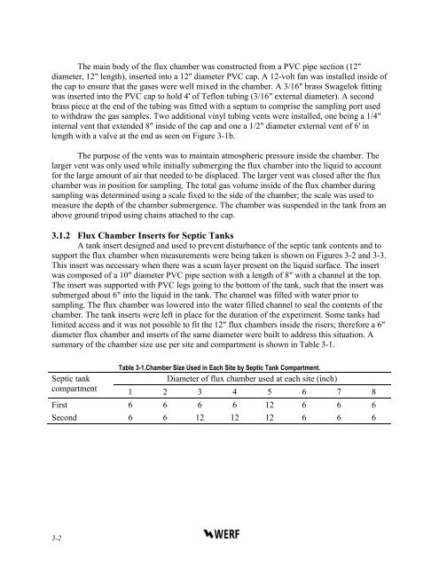
The main body <strong>of</strong> the flux chamber was constructed <strong>from</strong> a PVC pipe section (12"diameter, 12" length), inserted into a 12" diameter PVC cap. A 12-volt fan was installed inside <strong>of</strong>the cap to ensure that the gases were well mixed in the chamber. A 3/16" brass Swagelok fittingwas inserted into the PVC cap to hold 4' <strong>of</strong> Teflon tubing (3/16" external diameter). A secondbrass piece at the end <strong>of</strong> the tubing was fitted with a septum to comprise the sampling port usedto withdraw the gas samples. Two additional vinyl tubing vents were installed, one being a 1/4"internal vent that extended 8" inside <strong>of</strong> the cap and one a 1/2" diameter external vent <strong>of</strong> 6' inlength with a valve at the end as seen on Figure 3-1b.The purpose <strong>of</strong> the vents was to maintain atmospheric pressure inside the chamber. Thelarger vent was only used while initially submerging the flux chamber into the liquid to accountfor the large amount <strong>of</strong> air that needed to be displaced. The larger vent was closed after the fluxchamber was in position for sampling. The total gas volume inside <strong>of</strong> the flux chamber duringsampling was determined using a scale fixed to the side <strong>of</strong> the chamber; the scale was used tomeasure the depth <strong>of</strong> the chamber submergence. The chamber was suspended in the tank <strong>from</strong> anabove ground tripod using chains attached to the cap.3.1.2 Flux Chamber Inserts for <strong>Septic</strong> TanksA tank insert designed and used to prevent disturbance <strong>of</strong> the septic tank contents and tosupport the flux chamber when measurements were being taken is shown on Figures 3-2 and 3-3.This insert was necessary when there was a scum layer present on the liquid surface. The insertwas composed <strong>of</strong> a 10" diameter PVC pipe section with a length <strong>of</strong> 8" with a channel at the top.The insert was supported with PVC legs going to the bottom <strong>of</strong> the tank, such that the insert wassubmerged about 6" into the liquid in the tank. The channel was filled with water prior tosampling. The flux chamber was lowered into the water filled channel to seal the contents <strong>of</strong> thechamber. The tank inserts were left in place for the duration <strong>of</strong> the experiment. Some tanks hadlimited access and it was not possible to fit the 12" flux chambers inside the risers; therefore a 6"diameter flux chamber and inserts <strong>of</strong> the same diameter were built to address this situation. Asummary <strong>of</strong> the chamber size use per site and compartment is shown in Table 3-1.Table 3-1.Chamber Size Used in Each Site by <strong>Septic</strong> Tank Compartment.<strong>Septic</strong> tankDiameter <strong>of</strong> flux chamber used at each site (inch)compartment 1 2 3 4 5 6 7 8First 6 6 6 6 12 6 6 6Second 6 6 12 12 12 6 6 63-2


