II. Determining the Monitoring ApproachDetermining the monitoring approach<strong>for</strong> leak detection means making threekey choices about scope:• Areas or operations to haveseparate alarm and/or control• Types of systems (see Table 1 <strong>for</strong>details on the different types of<strong>TraceTek</strong> alarm modules).• Extent of leak detection coverageWhen deciding, consider theseimportant aspects of your application:the geometry, the response required toan alarm, the liquids to be detected,and the risks involved.Geometry/layoutApplication geometry is key indetermining the type of alarm moduleand number of units to use. Aspects ofthe application layout to consider includesize (length or area), separation (thenumber of separate pipes or areas), andaccessibility.ResponseWhen a leak occurs, consider how yourorganization must respond. If different groupsare responsible <strong>for</strong> different equipment,systems, or areas, use separate <strong>TraceTek</strong>alarm modules to make ownership clear.If you plan to use a <strong>TraceTek</strong> alarm module<strong>for</strong> direct equipment control (<strong>for</strong> example, toclose a valve when a leak is detected),select a module with relay logic that willprovide the desired operation, and useseparate modules to control separateequipment.Liquids to detectDifferent types of <strong>TraceTek</strong> sensing cablesare available to detect different types of liquids,as summarized in Table 2. To select asensing cable to detect a liquid not mentionedin Table 2 or the product data sheets,call Raychem <strong>for</strong> assistance. The sensingcables listed are compatible with all of thealarm modules, and multiple types of cablesmay be used in a single sensing circuit.RisksWhen deciding on the leak detectioncoverage <strong>for</strong> your application, take intoaccount the potential impact of a leak orspill, which could include injury, damage,cleanup costs, downtime, and liability. Alsoconsider the likelihood of leaks or spills,which depends heavily on applicationspecifics, such as the degree of exposureand the nature of the operations (thematerials handled, level of activity,maintenance practices).Hazardous locationsIf handling flammables, select <strong>TraceTek</strong>alarm modules and a system layout thatwill meet the approval requirements <strong>for</strong>your hazardous locations.Table 1. <strong>TraceTek</strong> Alarm Modules—Summary of FeaturesType of System Locating Multiple- Singlechannelalarmchannel alarm<strong>TraceTek</strong> Alarm Module TTDM TTG TTA-1 TTC-1<strong>Leak</strong> detection coverageAreas Number of branches/areas limited 4 with TTG-4 1 1only by length of sensing circuit 12 with TTG-12Max. sensing cable length 5000 ft (1500 m) 100 ft (30 m) per channel 100 ft (30 m) 100 ft (30 m)Alarm relaysType of Form C relay DPDT DPDT DPDT 4PDT 4PDT DPDT SPDTTriggered by <strong>Leak</strong> Serv. req'd. Fault <strong>Leak</strong> or fault on any channel <strong>Leak</strong> or fault <strong>Leak</strong> TroubleCommunication Relays, 4–20 mA analog, and Relay Relay Relayswith host systemsRS-232 or RS-485, ModbusEnclosure rating NEMA 12 NEMA 13 NEMA 1 NEMA 1Hazardous location usage*Module location Ordinary areas Ordinary areas or CID2 Ordinary areas Ordinary areasor CID2Sensing cable location Ordinary areas or CID2. Ordinary areas, CID2, or CID1 Ordinary areas, Ordinary areasCID1, if protected by approvedCID2, or CID1zener safety barrier.*See data sheets <strong>for</strong> details on approvals. CIDI stands <strong>for</strong> Class I, Division 1, CID2 stands <strong>for</strong> Class I Division 2 hazardous locations.Note: For additional in<strong>for</strong>mation, see page 5 of this guide or refer to the applicable product data sheets <strong>for</strong> complete detail.Table 2. <strong>TraceTek</strong> Sensing CablesSensing cable Liquids detected Liquids ignoredTT3000 Aqueous solutions and other conductive liquids Fuels and oilsTT5000 Fuels and oils: gasoline, diesel fuel, jet fuel, heating <strong>Water</strong> and aqueous solutionsoil, motor oil, hydraulic fluid, and other hydrocarbonsTT5001 Organic solvents: acetone, MEK, NMP, TCA, TCE <strong>Water</strong> and aqueous solutionsNotes: These sensing cables are compatible with any of the <strong>TraceTek</strong> alarm modules.Multiple types of cables may be used in a single sensing circuit.2
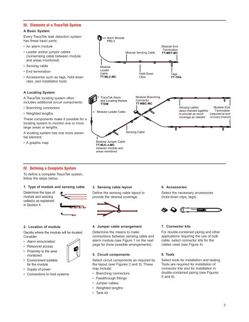
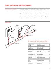
III. Elements of a <strong>TraceTek</strong> SystemA Basic SystemEvery <strong>TraceTek</strong> leak detection systemhas these basic parts:• An alarm module• Leader and/or jumper cables(nonsensing cable between moduleand areas monitored)• Sensing cable• End termination• Accessories such as tags, hold-downclips, and installation tools.Alarm ModuleTTC-1ModularLeaderCableTT-MLC-MCModular Sensing CableHold-DownClipsModular EndTerminationTT-MET-MCTagsTT-TAGA Locating SystemA <strong>TraceTek</strong> locating system often<strong>TraceTek</strong> Alarmand Locating Moduleincludes additional circuit components:TTDM• Branching connectorsModular Leader Cable• Weighted lengthsThese components make it possible <strong>for</strong> alocating system to monitor one or morelarge areas or lengths.A locating system has one more essentialelement:Sensing Cable• A graphic map Modular Jumper CableTT-MJC-x-MCbetween module andareas monitoredModular BranchingConnectorTT-MBC-MCSensing cablesModular Enddaisy-chained together Terminationto provide as much (required at endcoverage as needed of every branch)IV. Defining a Complete SystemTo define a complete <strong>TraceTek</strong> system,follow the steps below.1. Type of module and sensing cableDetermine the type ofmodule and sensingcable(s) as explainedin Section II.3. Sensing cable layoutDefine the sensing cable layout toprovide the desired coverage.6. AccessoriesSelect the necessary accessories(hold-down clips, tags).2. Location of moduleDecide where the module will be located.Consider:• Alarm annunciation• Personnel access• Proximity to the areamonitored• Environment suitable<strong>for</strong> the module• Supply of power• Connections to host systems4. Jumper cable arrangementDetermine the means to makeconnections between sensing cable andalarm module (see Figure 1 on the nextpage <strong>for</strong> three possible arrangements).5. Circuit componentsSelect circuit components as required bythe layout (see Figures 2 and 3). Thesemay include:• Branching connectors• Feedthrough fittings• Jumper cables• Weighted lengths• Tank kit7. Connector kitsFor double-contained piping and otherapplications requiring the use of bulkcable, select connector kits <strong>for</strong> thecables used (see Figure 4).8. ToolsSelect tools <strong>for</strong> installation and testing.Tools are required <strong>for</strong> installation ofconnector kits and <strong>for</strong> installation indouble-contained piping (see Figures5 and 6).3