ECEN 454 Digital Integrated Circuit Design Lab9
ECEN 454 Digital Integrated Circuit Design Lab9
ECEN 454 Digital Integrated Circuit Design Lab9
- No tags were found...
You also want an ePaper? Increase the reach of your titles
YUMPU automatically turns print PDFs into web optimized ePapers that Google loves.
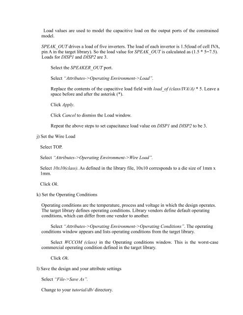
Load values are used to model the capacitive load on the output ports of the constrainedmodel.SPEAK_OUT drives a load of five inverters. The load of each invertor is 1.5(load of cell IVA,pin A in the target library). So the load value for SPEAK_OUT is calculated as (1.5 * 5=7.5).Loads for DISP1 and DISP2 are 3.Select the SPEAKER_OUT port.Select “Attributes->Operating Environment->Load”.Replace the contents of the capacitive load field with load_of (class/IVA/A) * 5. Leave aspace before and after the asterisk (*).Click Apply.Click Cancel to dismiss the Load window.Repeat the above steps to set capacitance load value on DISP1 and DISP2 to be 3.j) Set the Wire LoadSelect TOP.Select “Attributes->Operating Environment->Wire Load”.Select 10x10(class). As defined in the library file, 10x10 corresponds to a die size of 1mm x1mm.Click Ok.k) Set the Operating ConditionsOperating conditions are the temperature, process and voltage in which the design operates.The target library defines operating conditions. Library vendors define default operatingconditions, which can differ from one vendor to another.Select “Attributes->Operating Environment->Operating Conditions”. The operatingconditions window appears and lists operating conditions from the target library.Select WCCOM (class) in the Operating conditions window. This is the worst-casecommercial operating condition defined in the target library.Click Ok.l) Save the design and your attribute settingsSelect “File->Save As”.Change to your tutorial/db/ directory.


