PT-AE8000U PT-AT6000E PT-AE8000EA PT ... - Panasonic
PT-AE8000U PT-AT6000E PT-AE8000EA PT ... - Panasonic
PT-AE8000U PT-AT6000E PT-AE8000EA PT ... - Panasonic
Create successful ePaper yourself
Turn your PDF publications into a flip-book with our unique Google optimized e-Paper software.
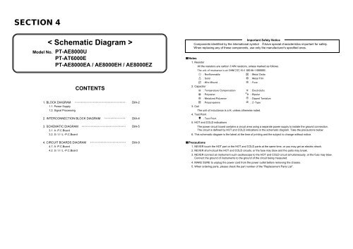
SECTION 4Important Safety Notice< Schematic Diagram > Components identified by the intemational symbol have special characteristics important for safety.Model No. <strong>PT</strong>-<strong>AE8000U</strong><strong>PT</strong>-<strong>AT6000E</strong><strong>PT</strong>-<strong>AE8000EA</strong> / AE8000EH / AE8000EZCONTENTS■Notes1. ResistorAll the resistors are carbon 1/4W resistors, unless marked as follows.The unit of resistance is an OHM [Ω] (K=1 000 M=1 000000).2. Capacitor: Nonflammable : Metal Oxide: Solid : Metal Film: Wire Wound : Fuse: Temperature Compensation : Electrolytic: Polyester : Bipolar: Metalized Polyester : Dipped Tantalum1. BLOCK DIAGRAM ・・・・・・・・・・・・・・・・・・・・・・・・・・・・・・・・・・ DIA-2 : Polypropylene : Z-Type1.1. Power Supply 3. Coil1.2. Signal Processing The unit of inductance is a H, unless otherwise noted.4. Test Point2. INTERCONNECTION BLOCK DIAGRAM ・・・・・・・・・・・・・・ DIA-4 : Test Point3. SCHEMATIC DIAGRAM ・・・・・・・・・・・・・・・・・・・・・・・・・・・・・・ DIA-53.1. A -P.C.BoardWhen replacing any of these components, use only the manufacturer's specified ones.5. HOT and COLD indicationsThe power circuit board contains a circuit area using a separate power supply to isolate the ground connection.The circuit is defined by HOT and COLD indications in the schematic diagram. Take the precautions below:3.2. S / V / L -P.C.Board 6. This schematic diagram is the latest at the time of printing and the subject to change without notice.4. CIRCUIT BOARDS DIAGRAM ・・・・・・・・・・・・・・・・・・・・・・・・ DIA-9 ■Precautions4.1. A -P.C.Board 1. NEVER touch the HOT part or the HOT and COLD parts at the same time, or you may get an electric shock.4.2. S / V / L -P.C.Board 2. NEVER short-circuit the HOT and COLD circuits, or the fuse may blow and the parts may break.3. NEVER connect an instrument such oscilloscope to the HOT and COLD circuit simultaneously, or the fuse may blow.Connect the ground of instruments to the ground of the circuit being measured.4. MAKE SURE to unplug the power cord from the power outlet before removing the chassis.5. When ordering parts, please check the part number of the "Replacement Parts List".


