CS5531/32/33/34 - Eshop-Rychle.cz
CS5531/32/33/34 - Eshop-Rychle.cz
CS5531/32/33/34 - Eshop-Rychle.cz

Create successful ePaper yourself
Turn your PDF publications into a flip-book with our unique Google optimized e-Paper software.
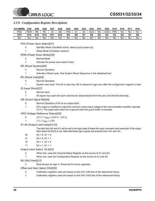
<strong>CS5531</strong>/<strong>32</strong>/<strong>33</strong>/<strong>34</strong>2.3.9. Configuration Register DescriptionsD31(MSB) D30 D29 D28 D27 D26 D25 D24 D23 D22 D21 D20 D19 D18 D17 D16PSS PDW RS RV IS GB VRS A1 A0 OLS NU OGS FRS NU NU NUD15 D14 D13 D12 D11 D10 D9 D8 D7 D6 D5 D4 D3 D2 D1 D0NU NU NU NU NU NU NU NU NU NU NU NU NU NU NU NUPSS (Power Save Select)[31]0 Standby Mode (Oscillator active, allows quick power-up).1 Sleep Mode (Oscillator inactive).PDW (Power Down Mode)[30]0 Normal Mode1 Activate the power save select mode.RS (Reset System)[29]0 Normal Operation.1 Activate a Reset cycle. See System Reset Sequence in the datasheet text.RV (Reset Valid)[28]0 Normal Operation1 System was reset. This bit is read only. Bit is cleared to logic zero after the configuration register is read.IS (Input Short)[27]0 Normal Input1 All signal input pairs for each channel are disconnected from the pins and shorted internally.GB (Guard Signal Bit)[26]0 Normal Operation of A0 as an output latch.1 A0’s output is modified to output the common mode output voltage of the instrumentation amplifier (typically2.5 V). The output latch select bit is ignored when the guard buffer is activated.VRS (Voltage Reference Select)[25]0 2.5 V < V REF ≤ [(VA+) - (VA-)]1 1 V ≤ V REF ≤ 2.5VA1-A0 (Output Latch bits)[24:23]The latch bits (A0 and A1) will be set to the logic state of these bits upon command word execution if the outputlatch select bit (OLS) is set. Note that these logic outputs are powered from VA+ and VA-.00 A0 = 0, A1 = 001 A0 = 0, A1 = 110 A0 = 1, A1 = 011 A0 = 1, A1 = 1Output Latch Select, OLS[22]0 When low, uses the Channel-Setup Register as the source of A1 and A0.1 When set, uses the Configuration Register as the source of A1 and A0.NU (Not Used)[21]0 Must always be logic 0. Reserved for future upgrades.Offset and Gain Select OGS[20]0 Calibration registers used are based on the CS1-CS0 bits of the referenced Setup.1 Calibration registers used are based on the OG1-OG0 bits of the referenced Setup.28 DS289PP5