CS5531/32/33/34 - Eshop-Rychle.cz
CS5531/32/33/34 - Eshop-Rychle.cz
CS5531/32/33/34 - Eshop-Rychle.cz

Create successful ePaper yourself
Turn your PDF publications into a flip-book with our unique Google optimized e-Paper software.
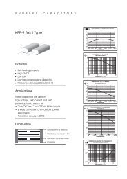
<strong>CS5531</strong>/<strong>32</strong>/<strong>33</strong>/<strong>34</strong>2.10. Clock GeneratorThe <strong>CS5531</strong>/<strong>32</strong>/<strong>33</strong>/<strong>34</strong> include an on-chip invertingamplifier which can be connected with an externalcrystal to provide the master clock for the chip. Figure20 illustrates the on-chip oscillator. It includesloading capacitors and a feedback resistor to forma Pierce oscillator configuration. The chips are designedto operate using a 4.9152 MHz crystal; however,other crystals with frequencies between 1MHz to 5 MHz can be used. One lead of the crystalshould be connected to OSC1 and the other toOSC2. Lead lengths should be minimized to reducestray capacitance. Note that while using the on-chiposcillator, neither OSC1 or OSC2 is capable of directlydriving any off chip logic. When the on-chiposcillator is used, the voltage on OSC2 is typically1/2 V peak-to-peak. This signal is not compatiblewith external logic unless additional external circuitryis added. The OSC2 output should be used ifthe on-chip oscillator output is used to drive othercircuitry.The designer can use an external CMOS compatibleoscillator to drive OSC2 with a 1 MHz to 5MHz clock for the ADC. The external clock intoOSC2 must overdrive the 60 microampere outputof the on-chip amplifier. This will not harm the onchipcircuitry. In this scheme, OSC1 should be leftunconnected.1 MΩ2.11. Power Supply ArrangementsThe <strong>CS5531</strong>/<strong>32</strong>/<strong>33</strong>/<strong>34</strong> are designed to operate fromsingle or dual analog supplies and a single digitalsupply. The following power supply connectionsare possible:VA+ = +5 V; VA- = 0 V; VD+ = +3 V to +5 VVA+=+2.5V;VA-=-2.5V;VD+=+3Vto+5VVA+ = +3 V; VA- = -3 V; VD+ = +3 VA VA+ supply of +2.5 V, +3.0 V, or +5.0 V shouldbe maintained at ±5% tolerance. A VA- supply of-2.5 V or -3.0 V should be maintained at ±5% tolerance.VD+ can extend from +2.7 V to +5.5 Vwith the additional restriction that [(VD+) - (VA-)