Pt B, Ch 12, Sec 2Table 1 : Resins’ mechanical characteristicsPolyester Vinylester EpoxyDensity ρ m 1,2 1,1 1,25Poisson coefficient ν m 0,38 0,26 0,39Tg (°C) around 60° around 100° between 80° and 150° (1)Tensile Young modulus (MPa) E m 3550 3350 3100Tensile or compressive breaking stress(MPa)55 75 75Tensile or compressive breaking strain (%) 1,8 2,2 2,5Shear modulus (MPa) G m 1350 1400 1500Shear breaking stress (MPa) around 50 around 65 around 80Shear breaking strain (%) 3,8 3,7 5(1) The actual value of Tg is depending on the polymerisation process used and in particular the temperature used in post-cure3.1.2 After fabrication of monofilaments and/or yarns, asurface treatment, named size, is carried on yarns in orderto:• create a cohesion between yarns• improve the quality of the reinforcement/resin interface• protect the yarns from manufacturing process.This size plays a very important part to promote fibre/resininterfacial bond strength. In some cases (carbon and paraaramidfibres), size remains on yarns throughout the fabrics’manufacturing process. In other cases (glass fibre), a firstsize is applied during yarns’ manufacturing to protectmonofilaments and a second one is applied during fabricfabrication to improve fibre/resin interface bonding characteristics.3.1.3 The linear density of a yarn, expressed in tex (g/km),has a direct influence on the strength of a yarn and then onfinal fabric.3.1.4 Taking into account that a reinforcement may beaffected by the nature of fibre, of yarn, of size or of fabricthe Surveyor may ask any useful justification such as technicaldata sheets of used yarns and/or fabrics to be submitted.3.1.5 As a general rule, mechanical tests are to be carry outon samples representative of hull laminate structure andpolymerisation process as defined in Ch 12, Sec 5, [4].At this stage, these tests aim at examining performance ofyarns and fabrics as well as the fibre/resin interface bondstrength.3.2 Fibre type3.2.1 GlassGlass monofilaments are obtained by heating a mixture ofsilica and alumina up to approximately 1600 °C then bystretching the liquid through a die, made up of holes generallyof 5 to 25 μm.They have the same molecular arrangement than glassplates and then are considered as isotropic materials. Itmeans that the mechanical properties are the same inlengthwise and crosswise directions.The two main types of glass used in composite shipbuildingare the E and the R types. E-glass is the reference glass, generallyused. R-glass has an higher mechanical resistancedue to greater percentages of silica and alumina in itschemical composition.Glass yarns have a standardized designation (ISO 2078),giving following information:• type of glass• type monofilament: C for Continuous and D for Discontinuous,commonly and respectively named strand andstaple• diameter of monofilaments in micrometer• linear density in Tex.For example, “EC15 800” means E-Glass made from Continuousmonofilaments of 15 μm diameter and 800 Tex.The main physical characteristics of the E-Glass are:• a good tensile and compressive strength and stiffness• a relatively poor impact resistance.The main physical characteristics of R-Glass are the samethan E-Glass with an improvement of roughly 20% as wellas good interlaminar shear strength properties.3.2.2 CarbonCarbon monofilaments are mainly made from Poly-Acrylonitril)(PAN) precursor fibres.PAN-precursor fibres are first oxidized (between 200°C and300°C) and then carbonized under inert atmosphere(between 700°C and 1500°C). These steps rearrange themolecular structure into a network of aromatic carbon layers,which are all chemically linked. This chemical processmakes the structure different in the lengthwise direction andin the crosswise direction, which explains the orthotropy ofcarbon monofilaments.This first stage of fabrication gives the HS Carbon.July 2006 with February 2008 Amendments Bureau Veritas Rules for Yachts 279
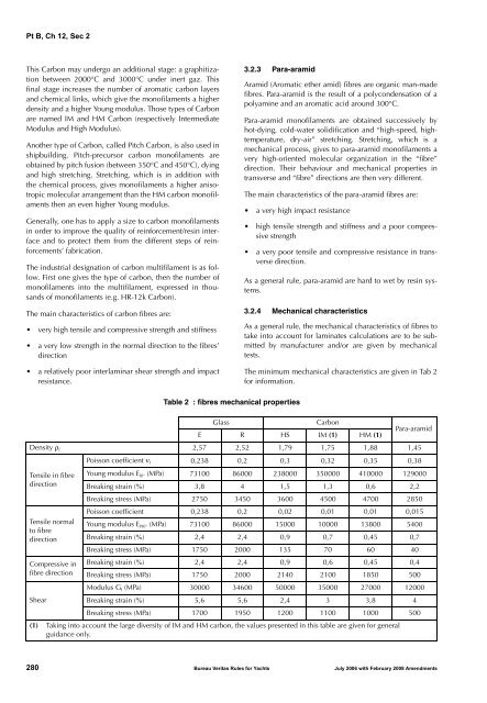
Pt B, Ch 12, Sec 2This Carbon may undergo an additional stage: a graphitizationbetween 2000°C and 3000°C under inert gaz. Thisfinal stage increases the number of aromatic carbon layersand chemical links, which give the monofilaments a higherdensity and a higher Young modulus. Those types of Carbonare named IM and HM Carbon (respectively IntermediateModulus and High Modulus).Another type of Carbon, called Pitch Carbon, is also used inshipbuilding. Pitch-precursor carbon monofilaments areobtained by pitch fusion (between 350°C and 450°C), dyingand high stretching. Stretching, which is in addition withthe chemical process, gives monofilaments a higher anisotropicmolecular arrangement than the HM carbon monofilamentsthen an even higher Young modulus.Generally, one has to apply a size to carbon monofilamentsin order to improve the quality of reinforcement/resin interfaceand to protect them from the different steps of reinforcements’fabrication.The industrial designation of carbon multifilament is as follow.First one gives the type of carbon, then the number ofmonofilaments into the multifilament, expressed in thousandsof monofilaments (e.g. HR-12k Carbon).The main characteristics of carbon fibres are:• very high tensile and compressive strength and stiffness• a very low strength in the normal direction to the fibres’direction• a relatively poor interlaminar shear strength and impactresistance.3.2.3 Para-aramidAramid (Aromatic ether amid) fibres are organic man-madefibres. Para-aramid is the result of a polycondensation of apolyamine and an aromatic acid around 300°C.Para-aramid monofilaments are obtained successively byhot-dying, cold-water solidification and “high-speed, hightemperature,dry-air” stretching. Stretching, which is amechanical process, gives to para-aramid monofilaments avery high-oriented molecular organization in the “fibre”direction. Their behaviour and mechanical properties intransverse and “fibre” directions are then very different.The main characteristics of the para-aramid fibres are:• a very high impact resistance• high tensile strength and stiffness and a poor compressivestrength• a very poor tensile and compressive resistance in transversedirection.As a general rule, para-aramid are hard to wet by resin systems.3.2.4 Mechanical characteristicsAs a general rule, the mechanical characteristics of fibres totake into account for laminates calculations are to be submittedby manufacturer and/or are given by mechanicaltests.The minimum mechanical characteristics are given in Tab 2for information.Table 2 : fibres mechanical propertiesGlassCarbonE R HS IM (1) HM (1)Para-aramidDensity ρ f 2,57 2,52 1,79 1,75 1,88 1,45Tensile in fibredirectionTensile normalto fibredirectionCompressive infibre directionShearPoisson coefficient ν f 0,238 0,2 0,3 0,32 0,35 0,38Young modulus E f0° (MPa) 73100 86000 238000 350000 410000 129000Breaking strain (%) 3,8 4 1,5 1,3 0,6 2,2Breaking stress (MPa) 2750 3450 3600 4500 4700 2850Poisson coefficient 0,238 0,2 0,02 0,01 0,01 0,015Young modulus E f90° (MPa) 73100 86000 15000 10000 13800 5400Breaking strain (%) 2,4 2,4 0,9 0,7 0,45 0,7Breaking stress (MPa) 1750 2000 135 70 60 40Breaking strain (%) 2,4 2,4 0,9 0,6 0,45 0,4Breaking stress (MPa) 1750 2000 2140 2100 1850 500Modulus G f (MPa) 30000 34600 50000 35000 27000 12000Breaking strain (%) 5,6 5,6 2,4 3 3,8 4Breaking stress (MPa) 1700 1950 1200 1100 1000 500(1) Taking into account the large diversity of IM and HM carbon, the values presented in this table are given for generalguidance only.280 Bureau Veritas Rules for Yachts July 2006 with February 2008 Amendments
- Page 1 and 2: A-PDF Merger DEMO : Purchase from w
- Page 3 and 4: Pt A, Ch 1, Sec 3SECTION 3SURVEYS1
- Page 5 and 6: Pt A, Ch 1, Sec 5SECTION 5INTERVENT
- Page 7 and 8: Pt A, Ch 2, Sec 1SECTION 1DEFINITIO
- Page 9 and 10: Pt A, Ch 2, Sec 2Table 3 : Charter
- Page 11 and 12: Pt B, Ch 1, Sec 1SECTION 1APPLICATI
- Page 13 and 14: Pt B, Ch 1, Sec 2SECTION 2SYMBOLS A
- Page 15 and 16: Pt B, Ch 1, Sec 4SECTION 4CALCULATI
- Page 17 and 18: Pt B, Ch 10, Sec 5SECTION 5INDEPEND
- Page 19 and 20: Pt B, Ch 11, Sec 1SECTION 1GENERAL
- Page 21 and 22: Pt B, Ch 12, Sec 2SECTION 2RAW MATE
- Page 23: Pt B, Ch 12, Sec 2The chemical netw
- Page 27 and 28: Pt B, Ch 12, Sec 23.4 Homologation
- Page 29 and 30: Pt B, Ch 12, Sec 2Table 4 : BalsaVo
- Page 31 and 32: Pt B, Ch 12, Sec 2Table 6 : Meta-ar
- Page 33 and 34: Pt B, Ch 12, Sec 3SECTION 3INDIVIDU
- Page 35 and 36: Pt B, Ch 12, Sec 3Table 1 : Resin /
- Page 37 and 38: Pt B, Ch 12, Sec 3Table 4 : Element
- Page 39 and 40: Pt B, Ch 3, Sec 1c) Lightweight che
- Page 41 and 42: Pt B, Ch 3, Sec 2Figure 1 : Severe
- Page 43 and 44: Pt B, Ch 3, Sec 2where:F : Wind for
- Page 45 and 46: Pt B, Ch 3, App 2APPENDIX 2TRIM AND
- Page 47 and 48: Pt B, Ch 4, Sec 2SECTION 2DESIGN LO
- Page 49 and 50: Pt B, Ch 6, Sec 3SECTION 3SPECIFIC
- Page 51 and 52: Pt B, Ch 6, Sec 3Figure 2 : Rig loa
- Page 53 and 54: Pt B, Ch 7, Sec 1SECTION 1 HYDRODYN
- Page 55 and 56: Pt B, Ch 7, Sec 1Figure 4 : Load ar
- Page 57 and 58: Pt B, Ch 7, Sec 1• for monohull -
- Page 59 and 60: Pt B, Ch 7, Sec 2SECTION 2BOTTOM SL
- Page 61 and 62: Pt B, Ch 9, Sec 1SECTION 1GENERAL1
- Page 63 and 64: Pt C, Ch 1, Sec 1Table 1 : Inclinat
- Page 65: Pt C, Ch 1, Sec 13.4 Safety devices