

SECTION 1 - Boat Design Net
SECTION 1 - Boat Design Net
SECTION 1 - Boat Design Net

You also want an ePaper? Increase the reach of your titles
YUMPU automatically turns print PDFs into web optimized ePapers that Google loves.
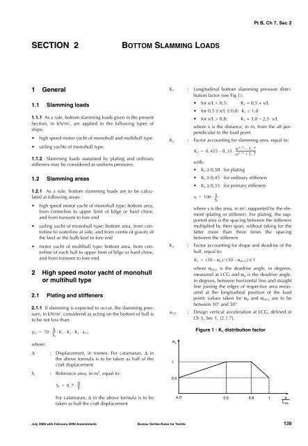
Pt B, Ch 7, Sec 2<strong>SECTION</strong> 2BOTTOM SLAMMING LOADS1 General1.1 Slamming loads1.1.1 As a ruIe, bottom slamming loads given in the presentSection, in kN/m 2 , are applied to the following types ofships:• high speed motor yacht of monohull and multihull type• sailing yachts of monohull type.1.1.2 Slamming loads sustained by plating and ordinarystiffeners may be considered as uniform pressures.1.2 Slamming areas1.2.1 As a rule, bottom slamming loads are to be calculatedat following areas:• high speed motor yacht of monohull type: bottom area,from centreline to upper limit of bilge or hard chine,and from transom to fore end• sailing yacht of monohull type: bottom area, from centrelineto waterline at side, and from centre of gravity ofthe keel or the bulb keel to fore end• motor yacht of multihull type: bottom area, from centrelineof each hull to upper limit of bilge or hard chine,and from transom to fore end.2 High speed motor yacht of monohullor multihull type2.1 Plating and stiffeners2.1.1 If slamming is expected to occur, the slamming pressure,in kN/m 2 , considered as acting on the bottom of hull isto be not less than:p sl = 70 ⋅ --- Δ ⋅K S1 ⋅ K 2 ⋅K 3 ⋅ a CGrwhere:Δ : Displacement, in tonnes. For catamaran, Δ inthe above formula is to be taken as half of thecraft displacementS r : Reference area, in m 2 , equal to:S r = 0,7 ⋅Δ -- TK 1 : Longitudinal bottom slamming pressure distributionfactor (see Fig 1):• for x/L < 0,5: K 1 = 0,5 + x/L• for 0,5 ≤ x/L ≤ 0,8: K 1 = 1,0• for x/L > 0,8: K 1 = 3,0 − 2,5 x/Lwhere x is the distance, in m, from the aft perpendicularto the load pointK 2 : Factor accounting for slamming area, equal to:K 2 0 455 0,35, – 1 ,= , – ⋅ --------------------------7, + 1 , 7with:u 0 75u 0 75• K 2 ≥ 0,50 for plating• K 2 ≥ 0,45 for ordinary stiffeners• K 2 ≥ 0,35 for primary stiffenersu = 100 ⋅ ---s S rwhere s is the area, in m 2 , supported by the element(plating or stiffener). For plating, the supportedarea is the spacing between the stiffenersmultiplied by their span, without taking for thelatter more than three times the spacingbetween the stiffenersK 3 : Factor accounting for shape and deadrise of thehull, equal to:K 3 = ( 50 – α d ) ⁄ ( 50 – α dCG ) ≤ 1where α dCG is the deadrise angle, in degrees,measured at LCG and α d is the deadrise angle,in degrees, between horizontal line and straightline joining the edges of respective area measuredat the longitudinal position of the loadpoint; values taken for α d and α dCG are to bebetween 10° and 30°a CG : <strong>Design</strong> vertical acceleration at LCG, defined inCh 5, Sec 1, [2.1.7].Figure 1 : K 1 distribution factorFor catamaran, Δ in the above formula is to betaken as half the craft displacementK 1110.5A.P.0.5 0.8xL WLJuly 2006 with February 2008 Amendments Bureau Veritas Rules for Yachts 139


