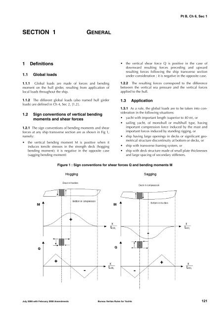
Pt B, Ch 6, Sec 1<strong>SECTION</strong> 1GENERAL1 Definitions1.1 Global loads1.1.1 Global loads are made of forces and bendingmoment on the hull girder, resulting from application oflocal loads throughout the ship.1.1.2 The different global loads (also named hull girderloads) are defined in Ch 4, Sec 2, [1.2].1.2 Sign conventions of vertical bendingmoments and shear forces1.2.1 The sign conventions of bending moments and shearforces at any ship transverse section are as shown in Fig 1,namely:• the vertical bending moment M is positive when itinduces tensile stresses in the strength deck (hoggingbending moment); it is negative in the opposite case(sagging bending moment)• the vertical shear force Q is positive in the case ofdownward resulting forces preceding and upwardresulting forces following the ship transverse sectionunder consideration ; it is negative in the opposite case.1.2.2 The resulting forces correspond to the differencebetween the vertical sea pressure and the vertical forcesapplied to the hull.1.3 Application1.3.1 As a rule, the global loads are to be taken into considerationin the following situations:• yacht with important length (superior to 40 m), or• sailing yacht, of monohull or multihull type, havingimportant compression force induced by the mast andimportant forces induced by standing rigging, or• ship having large openings in decks or significant geometricalstructure discontinuity at bottom or decks, or• ship with transverse framing system, or• ship with deck structure made of small plate thicknessesand large spacing of secondary stiffeners.Figure 1 : Sign conventions for shear forces Q and bending moments MJuly 2006 with February 2008 Amendments Bureau Veritas Rules for Yachts 121
Pt B, Ch 6, Sec 3<strong>SECTION</strong> 3SPECIFIC GLOBAL LOADS1 General1.1 Application1.1.1 The specific global loads of this Section are applicableto sailing yacht (monohull or catamaran) and to catamarans(sailing yachts or motor yachts).1.1.2 The multihulls with more than two floats are not coveredby the present Section and are to be submitted to aspecial examination.1.1.3 Other requirements may be considered for such specificglobal loads, in case of yachts having unusual particulars.2 Rig loads2.1 General2.1.1 The rig global loadings described in that Section aregenerally to be considered for yachts featuring:• a sailing configuration where mast, stays, shrouds andbackstay induce significant loads in the hull girder• a deck with large openings or significant structural discontinuity• a deck with transverse framing system.2.1.2 The rig global loads inducing a hull girder bendingeffect are to be combined with still water and wave globalloads as indicated in Ch 6, Sec 4.2.1.3 The rig loads to be considered in the present Sectionare the forces induced by the standing rigging:• stays• vertical shrouds and lower shrouds• backstay.The loads induced by the standing rigging during normalnavigation conditions are to be indicated by the Yard and/orby the <strong>Design</strong>er, for the various navigation conditions takingaccount of:• sails reduction versus apparent wind speed• sails configuration for all wind heading from head windto down wind.2.1.4 The combination calculations are carried out withoutany trim and list.2.1.5 The Society reserves the right to determine the rigloads from the sizing of the shrouds. In such case, the forcesare corresponding to the breaking strength of the shroudunder consideration, divided by a coefficient of 2,5 (thiscoefficient is generally the safety factor on breaking strengthused for the design of shrouds in the scantling riggings).The Society may consider a different value for this coefficient,on a case by case basis, upon satisfactory justificationgiven by the Yard and/or the <strong>Design</strong>er.2.2 Sailing monohull with one mast2.2.1 The maximum hull girder bending moment M RIG , inkN.m, induced by the standing rigging, is the mean value offore rig induced hull girder bending moment M RIGF and aftrig induced hull girder bending moment M RIGA , defined asfollows:• where only the forestay is loaded:M RIGF = F E sin α E L E• where only the baby stay is loaded:M RIGF = F BE sin α BE L BE• where both the main stay and the baby stay are loadedsimultaneously:M RIGF = F E sin α E L E + F BE sin α BE L BE• M RIGA = M P + M V1 + M D1where:M P = F P sin α P L PM V1 = F V1 L V1M D1 = F D1 sin α D1 L D1The symbols are shown on Fig 1, where:F P : Load on backstay, in kNF V1 : Load on vertical shroud, in kNF D1 : Load on lower shroud, in kNF E : Load on forestay, in kNF BE : Load on baby stay, in kNα I : Angle from the horizontal, in °, as shown on Fig 1L I : Horizontal distance from mast foot, in m, asshown on Fig 1.2.2.2 The maximum hull girder vertical shear force Q RIG , inkN, induced by the standing rigging, is the mean value offore rig induced hull girder vertical shear force Q RIGF and aftrig induced hull girder vertical shear force Q RIGA , defined asfollows:• where only the main stay is loaded:Q RIGF = F E sin α E• where only the baby stay is loaded:Q RIGF = F BE sin α BE• where both the main stay and the baby stay are loadedsimultaneously:Q RIGF = F E sin α E + F BE sin α BEJuly 2006 with February 2008 Amendments Bureau Veritas Rules for Yachts 125
- Page 1 and 2: A-PDF Merger DEMO : Purchase from w
- Page 3 and 4: Pt A, Ch 1, Sec 3SECTION 3SURVEYS1
- Page 5 and 6: Pt A, Ch 1, Sec 5SECTION 5INTERVENT
- Page 7 and 8: Pt A, Ch 2, Sec 1SECTION 1DEFINITIO
- Page 9 and 10: Pt A, Ch 2, Sec 2Table 3 : Charter
- Page 11 and 12: Pt B, Ch 1, Sec 1SECTION 1APPLICATI
- Page 13 and 14: Pt B, Ch 1, Sec 2SECTION 2SYMBOLS A
- Page 15 and 16: Pt B, Ch 1, Sec 4SECTION 4CALCULATI
- Page 17 and 18: Pt B, Ch 10, Sec 5SECTION 5INDEPEND
- Page 19 and 20: Pt B, Ch 11, Sec 1SECTION 1GENERAL
- Page 21 and 22: Pt B, Ch 12, Sec 2SECTION 2RAW MATE
- Page 23 and 24: Pt B, Ch 12, Sec 2The chemical netw
- Page 25 and 26: Pt B, Ch 12, Sec 2This Carbon may u
- Page 27 and 28: Pt B, Ch 12, Sec 23.4 Homologation
- Page 29 and 30: Pt B, Ch 12, Sec 2Table 4 : BalsaVo
- Page 31 and 32: Pt B, Ch 12, Sec 2Table 6 : Meta-ar
- Page 33 and 34: Pt B, Ch 12, Sec 3SECTION 3INDIVIDU
- Page 35 and 36: Pt B, Ch 12, Sec 3Table 1 : Resin /
- Page 37 and 38: Pt B, Ch 12, Sec 3Table 4 : Element
- Page 39 and 40: Pt B, Ch 3, Sec 1c) Lightweight che
- Page 41 and 42: Pt B, Ch 3, Sec 2Figure 1 : Severe
- Page 43 and 44: Pt B, Ch 3, Sec 2where:F : Wind for
- Page 45 and 46: Pt B, Ch 3, App 2APPENDIX 2TRIM AND
- Page 47: Pt B, Ch 4, Sec 2SECTION 2DESIGN LO
- Page 51 and 52: Pt B, Ch 6, Sec 3Figure 2 : Rig loa
- Page 53 and 54: Pt B, Ch 7, Sec 1SECTION 1 HYDRODYN
- Page 55 and 56: Pt B, Ch 7, Sec 1Figure 4 : Load ar
- Page 57 and 58: Pt B, Ch 7, Sec 1• for monohull -
- Page 59 and 60: Pt B, Ch 7, Sec 2SECTION 2BOTTOM SL
- Page 61 and 62: Pt B, Ch 9, Sec 1SECTION 1GENERAL1
- Page 63 and 64: Pt C, Ch 1, Sec 1Table 1 : Inclinat
- Page 65: Pt C, Ch 1, Sec 13.4 Safety devices