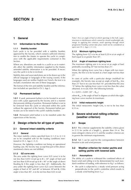
Pt B, Ch 3, Sec 2<strong>SECTION</strong> 2INTACT STABILITY1 General1.1 Information to the Master1.1.1 Stability bookletEach yacht is to be provided with a stability booklet,approved by the Society, which contains sufficient informationto enable the Master to operate the yacht in compliancewith the applicable requirements contained in thisSection.Where any alterations are made to a yacht so as to materiallyaffect the stability information supplied to the Master,amended stability information is to be provided. If necessarythe yacht is to be re-inclined.Stability data and associated plans are to be drawn up in theofficial language or languages of the issuing country. If thelanguages used are neither English nor French, the text is toinclude a translation into one of these languages.The format of the trim and stability booklet and the informationincluded are specified in Ch 3, App 2.1.2 Permanent ballast1.2.1 If used, permanent ballast is to be located in accordancewith a plan approved by the Society and in a mannerthat prevents shifting of position. Permanent ballast is not tobe removed from the yacht or relocated within the yachtwithout the approval of the Society. Permanent ballast particularsare to be noted in the yacht’s stability booklet.1.2.2 Permanent solid ballast is to be installed under thesupervision of the Society.2 <strong>Design</strong> criteria for all type of yachts2.1 General intact stability criteria2.1.1 GeneralThe intact stability criteria specified from [2.1.2] to [2.1.5]are to be complied with for the loading conditions mentionedin Ch 3, App 2, [1.2].However, the lightship condition not being an operationalloading case, the Society may accept that part of the abovementionedcriteria are not fulfilled.2.1.2 GZ curve areaThe area under the righting lever curve (GZ curve) is to benot less than 0,055 m . rad up to θ = 30° angle of heel andnot less than 0,09 m . rad up to θ = 40° or the angle of downflooding θ f if this angle is less than 40°. Additionally, thearea under the righting lever curve (GZ curve) between theangles of heel of 30° and 40° or between 30°and θ f , if thisangle is less than 40°, is to be not less than 0,03 m rad.Note 1: θ f is an angle of heel at which openings in the hull, superstructuresor deckhouses which cannot be closed weathertight submerge.In applying this criterion, small openings through whichprogressive flooding cannot take place need not be considered asopen (see Ch 3, App 2, [1.3.3]).2.1.3 Minimum righting leverThe righting lever GZ is to be at least 0,20 m at an angle ofheel equal to or greater than 30°.2.1.4 Angle of maximum righting leverThe maximum righting arm is to occur at an angle of heelpreferably exceeding 30° but not less than 25°.When the righting lever curve has a shape with two maximums,the first is to be located at a heel angle not less than25°.In cases of yachts with a particular design (multihull forexample), the Society may accept an angle of heel θ max lessthan 25° but in no case less than 10°, provided that the area“A” below the righting lever curve is not less than the valueobtained, in m.rad, from the following formula:A = 0,055 + 0,001 (30° − θ max )where θ max is the angle of heel in degrees at which the rightinglever curve reaches its maximum.2.1.5 Initial metacentric heightThe initial metacentric height GM 0 is not to be less than0,15 m.3 Severe wind and rolling criterion(weather criterion)3.1 Scope3.1.1 This criterion supplements the stability criteria givenin [2.1] for yachts of a length L LL greater than 24 m. Themore stringent criteria of [2.1] and the weather criterion areto govern the minimum requirements.3.1.2 Tab 1 can be used for the correspondence betweenBeaufort scale and wind pressure.3.2 Weather criterion for motor yachts andsailing yachts with lowered sails3.2.1 AssumptionsThe ability of a yacht to withstand the combined effects ofbeam wind and rolling is to be demonstrated for each standardcondition of loading, with reference to Fig 1 as follows:• the yacht is subjected to a steady wind pressure actingperpendicular to the yacht's centreline which results ina steady wind heeling lever (l w1 )July 2006 with February 2008 Amendments Bureau Veritas Rules for Yachts 89
Pt B, Ch 3, Sec 2Figure 1 : Severe wind and rollingg = 9,81m/s 2Table 1 : Beaufort scaleaLeverGZbl w1l w290θ 0Angle of heelθ 1θ 2 θ cBeaufort Wind pressure, in N/m 24 19 - 415 42 - 716 72 - 1187 119 - 1778 178 - 2559 256 - 36310 364 - 49111 492 - 648• from the resultant angle of equilibrium (θ 0 ), the yacht isassumed to roll owing to wave action to an angle of roll(θ 1 ) to windward• the yacht is then subjected to a gust wind pressurewhich results in a gust wind heeling lever (l w2 )• free surface effects, as described in [4], are to beaccounted for in the standard conditions of loading asset out in Ch 3, App 2, [1.2].UnrestrictednavigationRestrictednavigationTable 2 : Wind pressureL LL ≤ 70 mreduced pressureaccording to[3.2.4]reduced pressureaccording to[3.2.4]504 N/m 2L LL > 70 mreduced pressure subjectto the agreement ofthe Administration3.2.2 CriteriaUnder the assumptions of [3.2.1], the following criteria areto be complied with:• the area "b" is to be equal to or greater than area "a",where:a : area above the GZ curve and below l w2 ,between θ R and the intersection of l w2 withthe GZ curveb : area above the heeling lever l w2 and belowthe GZ curve, between the intersection ofl w2 with the GZ curve and θ 2• the angle of heel under action of steady wind (θ 0 ) is tobe limited to 16° or 80% of the angle of deck edgeimmersion, whichever is less.3.2.3 Heeling leversThe wind heeling levers l w1 and l w2 , in m, referred to in[3.2.2], should vary as the square cosine function of theyacht heel and should be calculated as follows:l W1 =PAZ--------------------1000gΔandl W2 = 1,5l W1where:P : Is according to Tab 2A : Projected lateral area in m 2 , of the portion of theyacht above the waterlineZ : Vertical distance in m, from the centre of A tothe centre of the underwater lateral area orapproximately to a point at one half the draughtΔ : Displacement in t.3.2.4 Calculation of the wind pressureFor yachts with a length equal or lesser than 70 m, the windpressure P, in t/m 2 , is to be calculated according to the followingformulae:Z – TP 0,0514⎛------------⎞ 1/3=⎝ 10 ⎠where :Z : Vertical distance in m, from the centre of A tothe centre of the underwater lateral area orapproximately to a point at one half the draughtT : Mean moulded draught in m, of the yacht.3.2.5 Angles of heelFor the purpose of calculating the criteria of [3.2.2], theangles in Fig 1 are defined as follows:θ 0 : Angle of heel, in degrees, under action of steadywindθ 1 : Angle of roll, in degress, to windward due towave action, calculated as follows:θ 1 = 109kX 1 X 2 rsθ 2 : Angle of downflooding θ f in degrees, or 50° orθ c , whichever is lessθ f : Angle of heel in degrees, at which openings inthe hull, superstructures or deckhouses whichcannot be closed weathertight immerse. Smallopenings though which progressive floodingcannot take place need not be considered asopen (see Ch 3, App 2, [1.3.3])θ c : Angle in degrees, of second intercept betweenwind heeling lever l w2 and GZ curves90 Bureau Veritas Rules for Yachts July 2006 with February 2008 Amendments
- Page 1 and 2: A-PDF Merger DEMO : Purchase from w
- Page 3 and 4: Pt A, Ch 1, Sec 3SECTION 3SURVEYS1
- Page 5 and 6: Pt A, Ch 1, Sec 5SECTION 5INTERVENT
- Page 7 and 8: Pt A, Ch 2, Sec 1SECTION 1DEFINITIO
- Page 9 and 10: Pt A, Ch 2, Sec 2Table 3 : Charter
- Page 11 and 12: Pt B, Ch 1, Sec 1SECTION 1APPLICATI
- Page 13 and 14: Pt B, Ch 1, Sec 2SECTION 2SYMBOLS A
- Page 15 and 16: Pt B, Ch 1, Sec 4SECTION 4CALCULATI
- Page 17 and 18: Pt B, Ch 10, Sec 5SECTION 5INDEPEND
- Page 19 and 20: Pt B, Ch 11, Sec 1SECTION 1GENERAL
- Page 21 and 22: Pt B, Ch 12, Sec 2SECTION 2RAW MATE
- Page 23 and 24: Pt B, Ch 12, Sec 2The chemical netw
- Page 25 and 26: Pt B, Ch 12, Sec 2This Carbon may u
- Page 27 and 28: Pt B, Ch 12, Sec 23.4 Homologation
- Page 29 and 30: Pt B, Ch 12, Sec 2Table 4 : BalsaVo
- Page 31 and 32: Pt B, Ch 12, Sec 2Table 6 : Meta-ar
- Page 33 and 34: Pt B, Ch 12, Sec 3SECTION 3INDIVIDU
- Page 35 and 36: Pt B, Ch 12, Sec 3Table 1 : Resin /
- Page 37 and 38: Pt B, Ch 12, Sec 3Table 4 : Element
- Page 39: Pt B, Ch 3, Sec 1c) Lightweight che
- Page 43 and 44: Pt B, Ch 3, Sec 2where:F : Wind for
- Page 45 and 46: Pt B, Ch 3, App 2APPENDIX 2TRIM AND
- Page 47 and 48: Pt B, Ch 4, Sec 2SECTION 2DESIGN LO
- Page 49 and 50: Pt B, Ch 6, Sec 3SECTION 3SPECIFIC
- Page 51 and 52: Pt B, Ch 6, Sec 3Figure 2 : Rig loa
- Page 53 and 54: Pt B, Ch 7, Sec 1SECTION 1 HYDRODYN
- Page 55 and 56: Pt B, Ch 7, Sec 1Figure 4 : Load ar
- Page 57 and 58: Pt B, Ch 7, Sec 1• for monohull -
- Page 59 and 60: Pt B, Ch 7, Sec 2SECTION 2BOTTOM SL
- Page 61 and 62: Pt B, Ch 9, Sec 1SECTION 1GENERAL1
- Page 63 and 64: Pt C, Ch 1, Sec 1Table 1 : Inclinat
- Page 65: Pt C, Ch 1, Sec 13.4 Safety devices