

SECTION 1 - Boat Design Net
SECTION 1 - Boat Design Net
SECTION 1 - Boat Design Net

You also want an ePaper? Increase the reach of your titles
YUMPU automatically turns print PDFs into web optimized ePapers that Google loves.
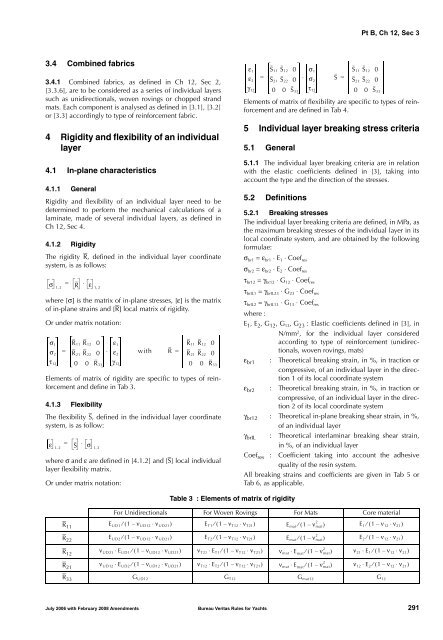
Pt B, Ch 12, Sec 33.4 Combined fabrics3.4.1 Combined fabrics, as defined in Ch 12, Sec 2,[3.3.6], are to be considered as a series of individual layerssuch as unidirectionals, woven rovings or chopped strandmats. Each component is analysed as defined in [3.1], [3.2]or [3.3] accordingly to type of reinforcement fabric.4 Rigidity and flexibility of an individuallayer4.1 In-plane characteristics4.1.1 GeneralRigidity and flexibility of an individual layer need to bedetermined to perform the mechanical calculations of alaminate, made of several individual layers, as defined inCh 12, Sec 4.4.1.2 RigidityThe rigidity R, defined in the individual layer coordinatesystem, is as follows:σ 12=, R ⋅ ε 1,2where [σ] is the matrix of in-plane stresses, [ε] is the matrixof in-plane strains and [R] local matrix of rigidity.Or under matrix notation:σ 1σ 2τ 12R 11 R 12 0R 21 R 22 00 0 R 33ε 1ε 2γ 12= ⋅ with R =Elements of matrix of rigidity are specific to types of reinforcementand define in Tab 3.4.1.3 FlexibilityThe flexibility S, defined in the individual layer coordinatesystem, is as follow:ε 1 2=, S ⋅ σ 1,2where σ and ε are defined in [4.1.2] and [S] local individuallayer flexibility matrix.Or under matrix notation:R 11 R 12 0R 21 R 22 00 0 R 33ε 1ε 2γ 12S 11 S 12 0S 21 S 22 00 0 S 33σ 1σ 2τ 12= ⋅ S =Elements of matrix of flexibility are specific to types of reinforcementand are defined in Tab 4.5 Individual layer breaking stress criteria5.1 General5.1.1 The individual layer breaking criteria are in relationwith the elastic coefficients defined in [3], taking intoaccount the type and the direction of the stresses.5.2 DefinitionsS 11 S 12 0S 21 S 22 00 0 S 335.2.1 Breaking stressesThe individual layer breaking criteria are defined, in MPa, asthe maximum breaking stresses of the individual layer in itslocal coordinate system, and are obtained by the followingformulae:σ br1 = ε br1 ⋅ E 1 ⋅ Coef resσ br2 = ε br2 ⋅ E 2 ⋅ Coef resτ br12 = γ br12 ⋅ G 12 ⋅ Coef resτ brIL1 = γ brIL23 ⋅ G 23 ⋅ Coef resτ brIL2 = γ brIL13 ⋅ G 13 ⋅ Coef reswhere :E 1 , E 2 , G 12 , G 13 , G 23 : Elastic coefficients defined in [3], inN/mm 2 , for the individual layer consideredaccording to type of reinforcement (unidirectionals,woven rovings, mats)ε br1 : Theoretical breaking strain, in %, in traction orcompressive, of an individual layer in the direction1 of its local coordinate systemε br2 : Theoretical breaking strain, in %, in traction orcompressive, of an individual layer in the direction2 of its local coordinate systemγ br12 : Theoretical in-plane breaking shear strain, in %,of an individual layerγ brIL : Theoretical interlaminar breaking shear strain,in %, of an individual layerCoef res : Coefficient taking into account the adhesivequality of the resin system.All breaking strains and coefficients are given in Tab 5 orTab 6, as applicable.Table 3 : Elements of matrix of rigidityFor Unidirectionals For Woven Rovings For Mats Core material2R 11E UD1 ⁄ ( 1 – ν UD12 ⋅ ν UD21 )E T1 ⁄ ( 1 – ν T12 ⋅ ν T21 )E mat ⁄ ( 1 – ν mat )E 1 ⁄ ( 1 – ν 12 ⋅ ν 21 )R 33 G UD12 G T12 G mat12 G 122R 22E UD2 ⁄ ( 1 – ν UD12 ⋅ ν UD21 )E T2 ⁄ ( 1 – ν T12 ⋅ ν T21 )E mat ⁄ ( 1 – ν mat )E 2 ⁄ ( 1 – ν 12 ⋅ ν 21 )2R 12ν UD21 ⋅ E UD1 ⁄ ( 1 – ν UD12 ⋅ ν UD21 ) ν T21 ⋅ E T1 ⁄ ( 1 – ν T12 ⋅ ν T21 ) ν mat ⋅ Emat ⁄ ( 1 – ν mat ) ν 21 ⋅ E 1 ⁄ ( 1 – ν 12 ⋅ ν 21 )2R 21ν UD12 ⋅ E UD2 ⁄ ( 1 – ν UD12 ⋅ ν UD21 ) ν T12 ⋅ E T2 ⁄ ( 1 – ν T12 ⋅ ν T21 ) ν mat ⋅ Emat ⁄ ( 1 – ν mat ) ν 12 ⋅ E 2 ⁄ ( 1 – ν 12 ⋅ ν 21 )July 2006 with February 2008 Amendments Bureau Veritas Rules for Yachts 291


