

TTS Golf RoToR oWNERS MANUAl - Hunter Industries
TTS Golf RoToR oWNERS MANUAl - Hunter Industries
TTS Golf RoToR oWNERS MANUAl - Hunter Industries

Create successful ePaper yourself
Turn your PDF publications into a flip-book with our unique Google optimized e-Paper software.
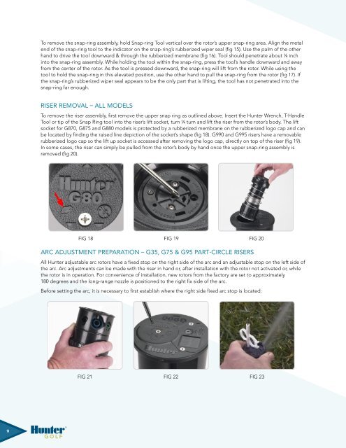
To remove the snap-ring assembly, hold Snap-ring Tool vertical over the rotor’s upper snap-ring area. Align the metalend of the snap-ring tool to the indicator on the snap-ring’s rubberized wiper seal (fig 15). Use the palm of the otherhand to drive the tool downward & through the rubberized membrane (fig 16). Tool should penetrate about ¼ inchinto the snap-ring assembly. While holding the tool within the snap-ring, press the tool’s handle downward and awayfrom the center of the rotor. As the tool is pressed downward, the snap-ring will lift from the rotor. While using thetool to hold the snap-ring in this elevated position, use the other hand to pull the snap-ring from the rotor (fig 17). Ifthe snap-ring’s rubberized wiper seal appears to be the only part that is lifting, the tool has not penetrated into thesnap-ring far enough.Riser Removal – All ModelsTo remove the riser assembly, first remove the upper snap ring as outlined above. Insert the <strong>Hunter</strong> Wrench, T-HandleTool or tip of the Snap Ring tool into the riser’s lift socket, turn ¼ turn and lift the riser from the rotor’s body. The liftsocket for G870, G875 and G880 models is protected by a rubberized membrane on the rubberized logo cap and canbe located by finding the raised line depiction of the socket’s shape (fig 18). G990 and G995 risers have a removablerubberized logo cap so the lift up socket is accessed after removing the logo cap, directly on top of the riser (fig 19).In some cases, the riser can simply be pulled from the rotor’s body by hand once the upper snap-ring assembly isremoved (fig 20).Fig 18 Fig 19 Fig 20Fig Arc 18 Adjustment Preparation Fig – G35, 19 G75 & G95 Part-Circle Risers Fig 20Fig Fig 18 18 Fig Fig 19 19 Fig Fig 20 20All <strong>Hunter</strong> adjustable arc rotors have a fixed stop on the right side of the arc and an adjustable stop on the left side ofthe arc. Arc adjustments can be made with the riser in hand or, after installation with the rotor not activated or, whilethe rotor is in operation. For convenience of installation, new rotors from the factory are set to approximately180 degrees and the long-range nozzle is positioned to the right fix side of the arc.Before setting the arc, it is necessary to first establish where the right side fixed arc stop is located:Fig 21 Fig 22 Fig 23Fig 22Fig 23Fig 249


