

TTS Golf RoToR oWNERS MANUAl - Hunter Industries
TTS Golf RoToR oWNERS MANUAl - Hunter Industries
TTS Golf RoToR oWNERS MANUAl - Hunter Industries

You also want an ePaper? Increase the reach of your titles
YUMPU automatically turns print PDFs into web optimized ePapers that Google loves.
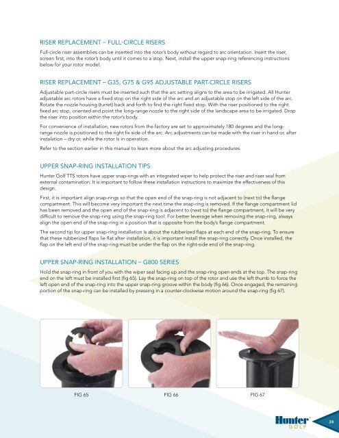
Riser Replacement – Full-Circle RisersFull-circle riser assemblies can be inserted into the rotor’s body without regard to arc orientation. Insert the riser,screen first, into the rotor’s body until it comes to a stop. Next, install the upper snap-ring referencing instructionsbelow for your rotor model.Riser Replacement – G35, G75 & G95 Adjustable Part-Circle RisersAdjustable part-circle risers must be inserted such that the arc setting aligns to the area to be irrigated. All <strong>Hunter</strong>adjustable arc rotors have a fixed stop on the right side of the arc and an adjustable stop on the left side of the arc.Rotate the nozzle housing (turret) back and forth to find the right fixed stop. With the riser positioned to the rightfixed arc stop, oriented and point the long-range nozzle to the right side of the landscape area to be irrigated. Dropthe riser into position within the rotor’s body.For convenience of installation, new rotors from the factory are set to approximately 180 degrees and the longrangenozzle is positioned to the right fix side of the arc. Arc adjustments can be made with the riser in hand or, afterinstalation – dry or, while the rotor is in operation.Refer to the section earlier in this manual to learn more about the arc adjusting procedures.Upper Snap-ring Installation Tips<strong>Hunter</strong> <strong>Golf</strong> <strong>TTS</strong> rotors have upper snap-rings with an integrated wiper to help protect the riser and riser seal fromexternal contamination. It is important to follow these installation instructions to maximize the effectiveness of thisdesign.First, it is important align snap-rings so that the open end of the snap-ring is not adjacent to (next to) the flangecompartment. This will become very important the next time the snap-ring is removed. If the flange compartment lidhas been removed and the open end of the snap-ring is adjacent to (next to) the flange compartment, it will be verydifficult to remove the snap-ring using the snap-ring tool. For better leverage when removing the snap-ring, alwaysalign the open end of the snap-ring in a position that is opposite from the body’s flange compartment.The second tip for upper snap-ring installation is about the rubberized flaps at each end of the snap-ring. To ensurethat these rubberized flaps lie flat after installation, it is important install the snap-ring correctly. Once installed, theflap on the left end of the snap-ring must be under the flap on the right-side end of the snap-ring.Upper Snap-ring Installation – G800 SeriesHold the snap-ring in front of you with the wiper seal facing up and the snap-ring open ends at the top. The snap-ringend on the left must be installed first (fig 65). Lay the snap-ring on top of the rotor and use the left thumb to force theleft open end of the snap-ring into the upper snap-ring groove within the body (fig 66). Once engaged, the remainingportion of the snap-ring can be installed by pressing in a counter-clockwise motion around the snap-ring (fig 67).Fig 65 Fig 66 Fig 67Fig Fig 65 65 65 Fig Fig 66 66 66 Fig 65 Fig 65 6524


