

TTS Golf RoToR oWNERS MANUAl - Hunter Industries
TTS Golf RoToR oWNERS MANUAl - Hunter Industries
TTS Golf RoToR oWNERS MANUAl - Hunter Industries

You also want an ePaper? Increase the reach of your titles
YUMPU automatically turns print PDFs into web optimized ePapers that Google loves.
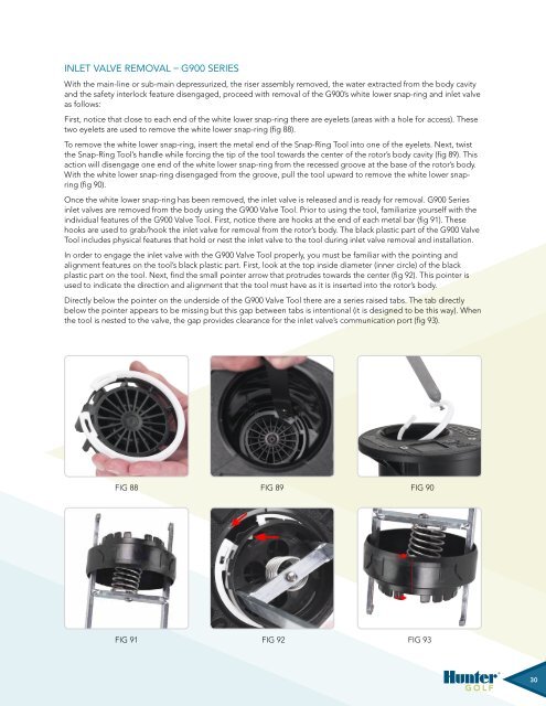
Inlet Valve Removal – G900 SeriesWith the main-line or sub-main depressurized, the riser assembly removed, the water extracted from the body cavityand the safety interlock feature disengaged, proceed with removal of the G900’s white lower snap-ring and inlet valveas follows:First, notice that close to each end of the white lower snap-ring there are eyelets (areas with a hole for access). Thesetwo eyelets are used to remove the white lower snap-ring (fig 88).To remove the white lower snap-ring, insert the metal end of the Snap-Ring Tool into one of the eyelets. Next, twistthe Snap-Ring Tool’s handle while forcing the tip of the tool towards the center of the rotor’s body cavity (fig 89). Thisaction will disengage one end of the white lower snap-ring from the recessed groove at the base of the rotor’s body.With the white lower snap-ring disengaged from the groove, pull the tool upward to remove the white lower snapring(fig 90).Once the white lower snap-ring has been removed, the inlet valve is released and is ready for removal. G900 Seriesinlet valves are removed from the body using the G900 Valve Tool. Prior to using the tool, familiarize yourself with theindividual features of the G900 Valve Tool. First, notice there are hooks at the end of each metal bar (fig 91). Thesehooks are used to grab/hook the inlet valve for removal from the rotor’s body. The black plastic part of the G900 ValveTool includes physical features that hold or nest the inlet valve to the tool during inlet valve removal and installation.In order to engage the inlet valve with the G900 Valve Tool properly, you must be familiar with the pointing andalignment features on the tool’s black plastic part. First, look at the top inside diameter (inner circle) of the blackplastic part on the tool. Next, find the small pointer arrow that protrudes towards the center (fig 92). This pointer isused to indicate the direction and alignment that the tool must have as it is inserted into the rotor’s body.Directly below the pointer on the underside of the G900 Valve Tool there are a series raised tabs. The tab directlybelow the pointer appears to be missing but this gap between tabs is intentional (it is designed to be this way). Whenthe tool is nested to the valve, the gap provides clearance for the inlet valve’s communication port (fig 93).Fig 88Fig 89Fig 90Fig 88 Fig 89 Fig 90Fig 91Fig 91Fig 91Fig 91Fig 92Fig 92Fig 92Fig 92Fig 93Fig 93Fig 93Fig 9330


