

TTS Golf RoToR oWNERS MANUAl - Hunter Industries
TTS Golf RoToR oWNERS MANUAl - Hunter Industries
TTS Golf RoToR oWNERS MANUAl - Hunter Industries

Create successful ePaper yourself
Turn your PDF publications into a flip-book with our unique Google optimized e-Paper software.
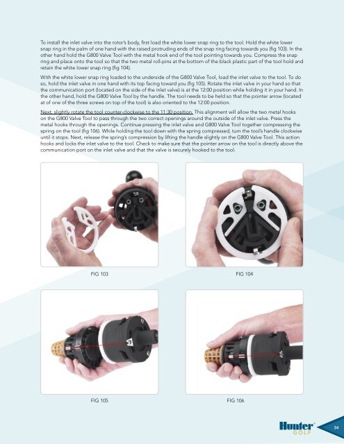
To install the inlet valve into the rotor’s body, first load the white lower snap ring to the tool. Hold the white lowersnap ring in the palm of one hand with the raised protruding ends of the snap ring facing towards you (fig 103). In theother hand hold the G800 Valve Tool with the metal hook end of the tool pointing towards you. Compress the snapring and place onto the tool so that the two metal roll-pins at the bottom of the black plastic part of the tool hold andretain the white lower snap ring (fig 104).With the white lower snap ring loaded to the underside of the G800 Valve Tool, load the inlet valve to the tool. To doso, hold the inlet valve in one hand with its top facing toward you (fig 105). Rotate the inlet valve in your hand so thatthe communication port (located on the side of the inlet valve) is at the 12:00 position while holding it in your hand. Inthe other hand, hold the G800 Valve Tool by the handle. The tool needs to be held so that the pointer arrow (locatedat of one of the three screws on top of the tool) is also oriented to the 12:00 position.Next, slightly rotate the tool counter-clockwise to the 11:30 position. This alignment will allow the two metal hookson the G800 Valve Tool to pass through the two correct openings around the outside of the inlet valve. Press themetal hooks through the openings. Continue pressing the inlet valve and G800 Valve Tool together compressing thespring on the tool (fig 106). While holding the tool down with the spring compressed, turn the tool’s handle clockwiseuntil it stops. Next, release the spring’s compression by lifting the handle slightly on the G800 Valve Tool. This actionhooks and locks the inlet valve to the tool. Check to make sure that the pointer arrow on the tool is directly above thecommunication port on the inlet valve and that the valve is securely hooked to the tool.Fig 103Fig 104Fig 102 Fig 102 Fig 103 Fig 103Fig 104 Fig 104 Fig 105 106Fig 105Fig 10534


