

TTS Golf RoToR oWNERS MANUAl - Hunter Industries
TTS Golf RoToR oWNERS MANUAl - Hunter Industries
TTS Golf RoToR oWNERS MANUAl - Hunter Industries

Create successful ePaper yourself
Turn your PDF publications into a flip-book with our unique Google optimized e-Paper software.
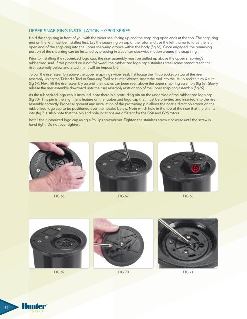
Upper Snap-ring Installation – G900 SeriesHold the snap-ring in front of you with the wiper seal facing up and the snap-ring open ends at the top. The snap-ringend on the left must be installed first. Lay the snap-ring on top of the rotor and use the left thumb to force the leftopen end of the snap-ring into the upper snap-ring groove within the body (fig 66). Once engaged, the remainingportion of the snap-ring can be installed by pressing in a counter-clockwise motion around the snap-ring.Prior to installing the rubberized logo cap, the riser assembly must be pulled up above the upper snap-ring’srubberized seal. If this procedure is not followed, the rubberized logo cap’s stainless steel screw cannot reach theriser assembly below and attachment will be impossible.To pull the riser assembly above the upper snap-ring’s wiper seal, first locate the lift-up socket on top of the riserassembly. Using the T-Handle Tool or Snap-ring Tool or <strong>Hunter</strong> Wrench, insert the tool into the lift-up socket, turn ¼ turn(fig 67). Next, lift the riser assembly up until the nozzles can been seen above the upper snap-ring assembly (fig 68). Slowlyrelease the riser assembly downward until the riser assembly rests on top of the upper snap-ring assembly (fig 69).As the rubberized logo cap is installed, note there is a protruding pin on the underside of the rubberized logo cap(fig 70). This pin is the alignment feature on the rubberized logo cap that must be oriented and inserted into the riserassembly correctly. Proper alignment and installation of the protruding pin allows the nozzle direction arrows on therubberized logo cap to be positioned over the nozzles below. Note which hole in the top of the riser that the pin fitsinto (fig 71). Also note that the pin and hole locations are different for the G90 and G95 rotors.Install the rubberized logo cap using a Phillips screwdriver. Tighten the stainless screw clockwise until the screw ishand tight. Do not over-tighten.Fig 66Fig 67Fig 68Fig Fig 66 66 Fig Fig 67 67 Fig Fig 686868Fig 66 Fig 67 Fig 68Fig 69Fig 70Fig 71Fig Fig 69 69 Fig Fig 70 70 Fig Fig 69 69Fig Fig 70Fig Fig 71 7170 Fig 71 7125


