

TTS Golf RoToR oWNERS MANUAl - Hunter Industries
TTS Golf RoToR oWNERS MANUAl - Hunter Industries
TTS Golf RoToR oWNERS MANUAl - Hunter Industries

Create successful ePaper yourself
Turn your PDF publications into a flip-book with our unique Google optimized e-Paper software.
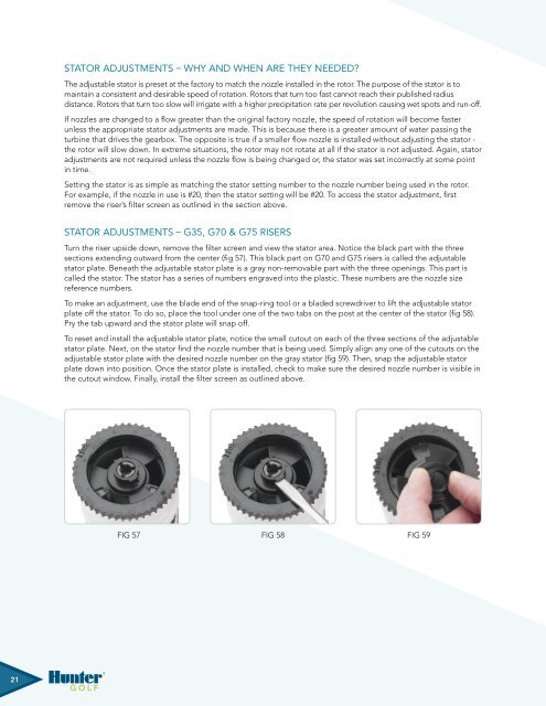
Stator Adjustments – Why and When Are They Needed?The adjustable stator is preset at the factory to match the nozzle installed in the rotor. The purpose of the stator is tomaintain a consistent and desirable speed of rotation. Rotors that turn too fast cannot reach their published radiusdistance. Rotors that turn too slow will irrigate with a higher precipitation rate per revolution causing wet spots and run-off.If nozzles are changed to a flow greater than the original factory nozzle, the speed of rotation will become fasterunless the appropriate stator adjustments are made. This is because there is a greater amount of water passing theturbine that drives the gearbox. The opposite is true if a smaller flow nozzle is installed without adjusting the stator -the rotor will slow down. In extreme situations, the rotor may not rotate at all if the stator is not adjusted. Again, statoradjustments are not required unless the nozzle flow is being changed or, the stator was set incorrectly at some pointin time.Setting the stator is as simple as matching the stator setting number to the nozzle number being used in the rotor.For example, if the nozzle in use is #20, then the stator setting will be #20. To access the stator adjustment, firstremove the riser’s filter screen as outlined in the section above.Stator Adjustments – G35, G70 & G75 RisersTurn the riser upside down, remove the filter screen and view the stator area. Notice the black part with the threesections extending outward from the center (fig 57). This black part on G70 and G75 risers is called the adjustablestator plate. Beneath the adjustable stator plate is a gray non-removable part with the three openings. This part iscalled the stator. The stator has a series of numbers engraved into the plastic. These numbers are the nozzle sizereference numbers.To make an adjustment, use the blade end of the snap-ring tool or a bladed screwdriver to lift the adjustable statorplate off the stator. To do so, place the tool under one of the two tabs on the post at the center of the stator (fig 58).Pry the tab upward and the stator plate will snap off.To reset and install the adjustable stator plate, notice the small cutout on each of the three sections of the adjustablestator plate. Next, on the stator find the nozzle number that is being used. Simply align any one of the cutouts on theadjustable stator plate with the desired nozzle number on the gray stator (fig 59). Then, snap the adjustable statorplate down into position. Once the stator plate is installed, check to make sure the desired nozzle number is visible inthe cutout window. Finally, install the filter screen as outlined above.Fig 57 Fig 58 Fig 59Fig Fig 57 57 Fig 57 Fig Fig 58 58 Fig 58 Fig Fig 59 59 Fig 5921


