

TTS Golf RoToR oWNERS MANUAl - Hunter Industries
TTS Golf RoToR oWNERS MANUAl - Hunter Industries
TTS Golf RoToR oWNERS MANUAl - Hunter Industries

You also want an ePaper? Increase the reach of your titles
YUMPU automatically turns print PDFs into web optimized ePapers that Google loves.
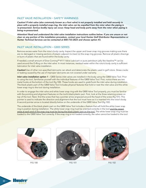
Inlet Valve Installation – Safety WarningsCaution! If inlet valve (also commonly known as a foot valve) is not properly installed and held securely inplace with a properly installed snap-ring, the inlet valve can be expelled from the rotor when the piping isre-pressurized. Serious bodily injury can occur. Keep head and body parts away from the rotor when piping isbeing re-pressurized.Attention! Read and understand the inlet valve installation instructions outline below. If you are unsure or notclear on any portion of the installation procedure, contact your local <strong>Hunter</strong> <strong>Golf</strong> Distributor Representative or<strong>Hunter</strong> Technical Services can be contacted at 800-733-2823 and choose option #3.Inlet Valve Installation – G800 SeriesRemove excess water from the rotor’s body cavity. Inspect the upper and lower snap ring grooves making sure thereare no damaged or missing sections of plastic adjacent to (next to) the snap ring grooves. Remove all plastic shavingsor burrs of plastic that are found within the body cavity.If needed, a small amount of Dow Corning #111 Valve Lubricant or pure petroleum jelly like Vaseline can beused around the O-Ring on the inlet valve. In most instances, residual water within the rotor’s body cavity is sufficientlubrication for inlet valve installation.Caution! Use of other non-specified lubricants can attack and deteriorate the plastic used in golf rotors. Stress cracksor leaking caused by the use of improper lubricants are not covered under warranty.Inlet valve installation option 1 – G800 Series inlet valves are installed in the body using the G800 Valve Tool. Priorto using the tool, familiarize yourself with the individual features of the G800 Valve Tool. First, notice there are twometal hooks at the bottom of the tool (fig 100). These hooks are used to grab/hook the inlet valve during installation.The black plastic part of the G800 Valve Tool includes physical features that hold or nest the inlet valve and the whitelower snap ring to the tool during installation.In order to engage the inlet valve and white lower snap ring with the G800 Valve Tool properly, you must be familiarwith the pointing and alignment features on the tool’s black plastic part. First, look at the three retaining screws ontop of the tool. Next, find the screw that has a pointer arrow engraved around the head of the screw (fig 101). Thispointer is used to indicate the direction and alignment that the tool must have as it is inserted into the rotor’s body.A second pointer arrow is located directly below on the underside of the G800 Valve Tool (fig 102).The underside of the black plastic part on the G800 Valve Tool includes a feature that will hold the white lower snapring in position during installation. The white lower snap ring must be oriented correctly in the tool and the raisedareas at each end of the snap ring must be facing the black plastic part on the tool. The white lower snap ring must beloaded to the G800 Valve Tool correctly. If the snap ring is not loaded correctly, the valve cannot be loaded to the tool.Fig 100 Fig 101 Fig 102Fig 99 Fig 100 Fig 101Fig Fig 99 99 Fig Fig 100 100 Fig Fig 101 10133


