

TTS Golf RoToR oWNERS MANUAl - Hunter Industries
TTS Golf RoToR oWNERS MANUAl - Hunter Industries
TTS Golf RoToR oWNERS MANUAl - Hunter Industries

You also want an ePaper? Increase the reach of your titles
YUMPU automatically turns print PDFs into web optimized ePapers that Google loves.
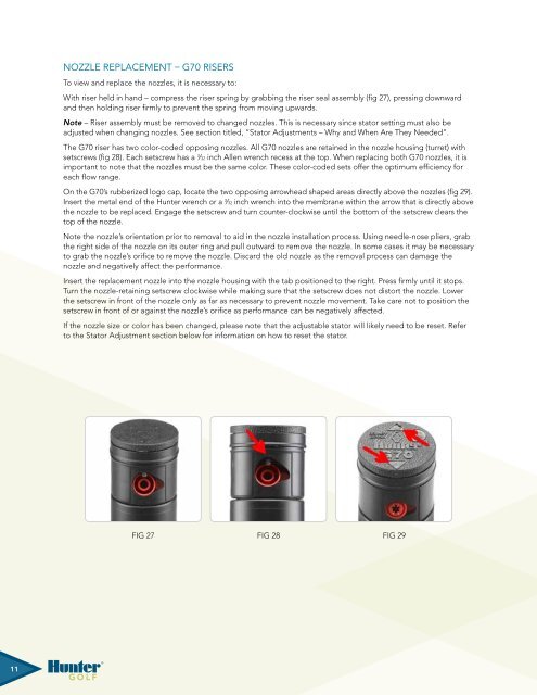
Nozzle Replacement – G70 RisersTo view and replace the nozzles, it is necessary to:With riser held in hand – compress the riser spring by grabbing the riser seal assembly (fig 27), pressing downwardand then holding riser firmly to prevent the spring from moving upwards.Note – Riser assembly must be removed to changed nozzles. This is necessary since stator setting must also beadjusted when changing nozzles. See section titled, “Stator Adjustments – Why and When Are They Needed”.The G70 riser has two color-coded opposing nozzles. All G70 nozzles are retained in the nozzle housing (turret) withsetscrews (fig 28). Each setscrew has a 3 ⁄32 inch Allen wrench recess at the top. When replacing both G70 nozzles, it isimportant to note that the nozzles must be the same color. These color-coded sets offer the optimum efficiency foreach flow range.On the G70’s rubberized logo cap, locate the two opposing arrowhead shaped areas directly above the nozzles (fig 29).Insert the metal end of the <strong>Hunter</strong> wrench or a 3 ⁄32 inch wrench into the membrane within the arrow that is directly abovethe nozzle to be replaced. Engage the setscrew and turn counter-clockwise until the bottom of the setscrew clears thetop of the nozzle.Note the nozzle’s orientation prior to removal to aid in the nozzle installation process. Using needle-nose pliers, grabthe right side of the nozzle on its outer ring and pull outward to remove the nozzle. In some cases it may be necessaryto grab the nozzle’s orifice to remove the nozzle. Discard the old nozzle as the removal process can damage thenozzle and negatively affect the performance.Insert the replacement nozzle into the nozzle housing with the tab positioned to the right. Press firmly until it stops.Turn the nozzle-retaining setscrew clockwise while making sure that the setscrew does not distort the nozzle. Lowerthe setscrew in front of the nozzle only as far as necessary to prevent nozzle movement. Take care not to position thesetscrew in front of or against the nozzle’s orifice as performance can be negatively affected.If the nozzle size or color has been changed, please note that the adjustable stator will likely need to be reset. Referto the Stator Adjustment section below for information on how to reset the stator.Fig 27 Fig 28 Fig 29Fig 28 Fig 28 Fig 29 Fig 29Fig 2711


