SERVICE MANUAL SERIES 360 EP SERIES 360 ES - Precisa
SERVICE MANUAL SERIES 360 EP SERIES 360 ES - Precisa
SERVICE MANUAL SERIES 360 EP SERIES 360 ES - Precisa

Create successful ePaper yourself
Turn your PDF publications into a flip-book with our unique Google optimized e-Paper software.
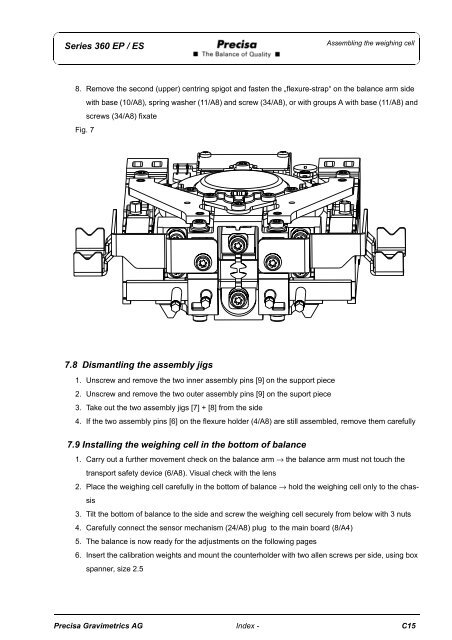
Series <strong>360</strong> <strong>EP</strong> / <strong>ES</strong>Assembling the weighing cell8. Remove the second (upper) centring spigot and fasten the „flexure-strap“ on the balance arm sidewith base (10/A8), spring washer (11/A8) and screw (34/A8), or with groups A with base (11/A8) andscrews (34/A8) fixateFig. 77.8 Dismantling the assembly jigs1. Unscrew and remove the two inner assembly pins [9] on the support piece2. Unscrew and remove the two outer assembly pins [9] on the suport piece3. Take out the two assembly jigs [7] + [8] from the side4. If the two assembly pins [6] on the flexure holder (4/A8) are still assembled, remove them carefully7.9 Installing the weighing cell in the bottom of balance1. Carry out a further movement check on the balance arm → the balance arm must not touch thetransport safety device (6/A8). Visual check with the lens2. Place the weighing cell carefully in the bottom of balance → hold the weighing cell only to the chassis3. Tilt the bottom of balance to the side and screw the weighing cell securely from below with 3 nuts4. Carefully connect the sensor mechanism (24/A8) plug to the main board (8/A4)5. The balance is now ready for the adjustments on the following pages6. Insert the calibration weights and mount the counterholder with two allen screws per side, using boxspanner, size 2.5<strong>Precisa</strong> Gravimetrics AG Index - C15