

The IT earthing system (unearthed neutral) in LV
The IT earthing system (unearthed neutral) in LV
The IT earthing system (unearthed neutral) in LV

You also want an ePaper? Increase the reach of your titles
YUMPU automatically turns print PDFs into web optimized ePapers that Google loves.
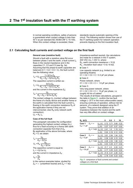
2 <strong>The</strong> 1 st <strong>in</strong>sulation fault with the <strong>IT</strong> <strong>earth<strong>in</strong>g</strong> <strong>system</strong>In normal operat<strong>in</strong>g conditions, safety of personsis guaranteed when contact voltage is less than50 V as per standard IEC 60364 (NF C 15-100).When this contact voltage is exceeded, thesestandards require automatic open<strong>in</strong>g of thecircuit. <strong>The</strong> follow<strong>in</strong>g section shows how use ofthe <strong>IT</strong> <strong>earth<strong>in</strong>g</strong> <strong>system</strong> for network operationprevents tripp<strong>in</strong>g on the first <strong>in</strong>sulation fault.2.1 Calculat<strong>in</strong>g fault currents and contact voltage on the first faultGeneral case (resistive fault)Should a fault with a resistive value Rd occurbetween phase 3 and the earth, a fault current I dflows <strong>in</strong> the neutral impedance and <strong>in</strong> thecapacities C1, C2 and C3 (see fig. 3a).Assum<strong>in</strong>g that the phase-to-earth capacities arebalanced (C1 = C2 = C3 = C), the fault currenthas the follow<strong>in</strong>g value:1+ 3j CωZI d =UN0Rd+ ZN + 3jCωZNRd<strong>The</strong> capacitive current is written as:3j CωZI c =UN0Rd+ ZN + 3jCωZNRdand the current <strong>in</strong> the impedance Z N :UI N =0Rd+ ZN + 3jCωZNRd<strong>The</strong> contact voltage U C (contact voltage betweenthe frame of a faulty device and another frame orthe earth) is calculated from the fault current I dflow<strong>in</strong>g <strong>in</strong> the earth connection resistance R A ofthe application frames if they are not<strong>in</strong>terconnected, else R B (only network earthconnection):U C = R A I d .Case of the full faultThis paragraph calculates the configurationgenerat<strong>in</strong>g the highest contact voltage (U C ):thus for a fault occur<strong>in</strong>g on a frame with earthconnection separate from that of Z N .By application of the above formulae, whereR d = 0, we obta<strong>in</strong>:UI d = 0ZN+ 3j CωUUc = R 0AZ N + 3j Cω<strong>The</strong> capacitive current is equal to:I C = +3j Cω U 0and the current <strong>in</strong> impedance Z N :UI N = 0ZNIn the various examples below, studied forZ N = ∞ (<strong>unearthed</strong> neutral) and Z N = 1 kΩ(impedance-earthed neutral), the calculationsare made for a network <strong>in</strong> the <strong>IT</strong> <strong>system</strong>,400 VAC (U 0 = 230 V), where:R A , earth connection resistance = 10 ΩR d , <strong>in</strong>sulation fault value = 0 to 10 kΩ.c Case 1:Low capacity network (e.g. limited to anoperat<strong>in</strong>g theatre)C1 = C2 = C3 = C = 0.3 µF per phase.c Case 2:Power network, whereC1 = C2 = C3 = C = 1.6 µF per phase.c Case 3:Very long power network, whereC1 = C2 = C3 = C = 10 µF per phase, i.e.roughly 40 km of cables!<strong>The</strong> results of all these calculations, grouped <strong>in</strong>the table <strong>in</strong> figure 5 , confirm the low faultvoltage (≈ 20 V <strong>in</strong> the most unfavourable cases),ensur<strong>in</strong>g cont<strong>in</strong>uity of operation, without risk forpersons, of a network designed us<strong>in</strong>g the <strong>IT</strong><strong>system</strong>. <strong>The</strong>y prove that addition of animpedance between the neutral and the earthhas very little effect on contact voltage.R d (kΩ) 0 0.5 1 10Case 1 Z N = ∞ U C (V) 0.72 0.71 0.69 0.22C R =1µF I d (A) 0.07 0.07 0.07 0.02Z N = 1 kΩ U C (V) 2.41 1.6 1.19 0.21I d (A) 0.24 0.16 0.12 0.02Case 2 Z N = ∞ U C (V) 3.61 2.84 1.94 0.23C R =5µF I d (A) 0.36 0.28 0.19 0.02Z N = 1 kΩ U C (V) 4.28 2.53 1.68 0.22I d (A) 0.43 0.25 0.17 0.02Case 3 Z N = ∞ U C (V) 21.7 4.5 2.29 0.23C R =30µF I d (A) 2.17 0.45 0.23 0.02Z N = 1 kΩ U C (V) 21.8 4.41 2.26 0.23I d (A) 2.18 0.44 0.23 0.02Fig. 5 : comparison of fault currents and contactvoltages on a first fault.Cahier Technique Schneider Electric no. 178 / p.9


