

The IT earthing system (unearthed neutral) in LV
The IT earthing system (unearthed neutral) in LV
The IT earthing system (unearthed neutral) in LV

You also want an ePaper? Increase the reach of your titles
YUMPU automatically turns print PDFs into web optimized ePapers that Google loves.
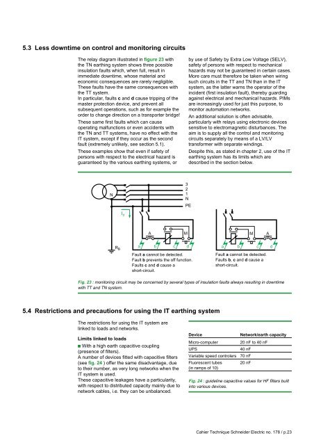
5.3 Less downtime on control and monitor<strong>in</strong>g circuits<strong>The</strong> relay diagram illustrated <strong>in</strong> figure 23 withthe TN <strong>earth<strong>in</strong>g</strong> <strong>system</strong> shows three possible<strong>in</strong>sulation faults which, when full, result <strong>in</strong>immediate downtime, whose material andeconomic consequences are rarely negligible.<strong>The</strong>se faults have the same consequences withthe TT <strong>system</strong>.In particular, faults c and d cause tripp<strong>in</strong>g of themaster protection device, and prevent allsubsequent operations, such as for example theorder to change direction on a transporter bridge!<strong>The</strong>se same first faults which can causeoperat<strong>in</strong>g malfunctions or even accidents withthe TN and TT <strong>system</strong>s, have no effect with the<strong>IT</strong> <strong>system</strong>, except if they occur as the secondfault (extremely unlikely, see section 5.1).<strong>The</strong>se examples show that even if safety ofpersons with respect to the electrical hazard isguaranteed by the various <strong>earth<strong>in</strong>g</strong> <strong>system</strong>s, orby use of Safety by Extra Low Voltage (SE<strong>LV</strong>),safety of persons with respect to mechanicalhazards may not be guaranteed <strong>in</strong> certa<strong>in</strong> cases.More care must therefore be taken when wir<strong>in</strong>gsuch circuits <strong>in</strong> the TT and TN than <strong>in</strong> the <strong>IT</strong><strong>system</strong>, as the latter warns the operator of the<strong>in</strong>cident (first <strong>in</strong>sulation fault), thereby guard<strong>in</strong>gaga<strong>in</strong>st electrical and mechanical hazards. PIMsare <strong>in</strong>creas<strong>in</strong>gly used for just this purpose, tomonitor automation networks.An additional solution is often advisable,particularly with relays us<strong>in</strong>g electronic devicessensitive to electromagnetic disturbances. <strong>The</strong>aim is to supply all the control and monitor<strong>in</strong>gcircuits separately by means of a <strong>LV</strong>/<strong>LV</strong>transformer with separate w<strong>in</strong>d<strong>in</strong>gs.Despite this, as stated <strong>in</strong> chapter 2, use of the <strong>IT</strong><strong>earth<strong>in</strong>g</strong> <strong>system</strong> has its limits which aredescribed <strong>in</strong> the section below.32N1NPEI dAMR a b c dBFault a cannot be detected.Fault b prevents the off function.Faults c and d cause ashort-circuit.Ma b c dFault a cannot be detected.Faults b, c and d cause ashort-circuit.AFig. 23 : monitor<strong>in</strong>g circuit may be concerned by several types of <strong>in</strong>sulation faults always result<strong>in</strong>g <strong>in</strong> downtimewith TT and TN <strong>system</strong>.5.4 Restrictions and precautions for us<strong>in</strong>g the <strong>IT</strong> <strong>earth<strong>in</strong>g</strong> <strong>system</strong><strong>The</strong> restrictions for us<strong>in</strong>g the <strong>IT</strong> <strong>system</strong> arel<strong>in</strong>ked to loads and networks.Limits l<strong>in</strong>ked to loadsc With a high earth capacitive coupl<strong>in</strong>g(presence of filters).A number of devices fitted with capacitive filters(see fig. 24 ) offer the same disadvantage, dueto their number, as very long networks when the<strong>IT</strong> <strong>system</strong> is used.<strong>The</strong>se capacitive leakages have a particularity,with respect to distributed capacity ma<strong>in</strong>ly due tonetwork cables, i.e. they can be unbalanced.DeviceMicro-computerUPSVariable speed controlersFluorescent tubes(<strong>in</strong> ramps of 10)Network/earth capacity20 nF to 40 nF40 nF70 nF20 nFFig. 24 : guidel<strong>in</strong>e capacitive values for HF filters built<strong>in</strong>to various devices.Cahier Technique Schneider Electric no. 178 / p.23


