The IT earthing system (unearthed neutral) in LV
The IT earthing system (unearthed neutral) in LV
The IT earthing system (unearthed neutral) in LV
Create successful ePaper yourself
Turn your PDF publications into a flip-book with our unique Google optimized e-Paper software.
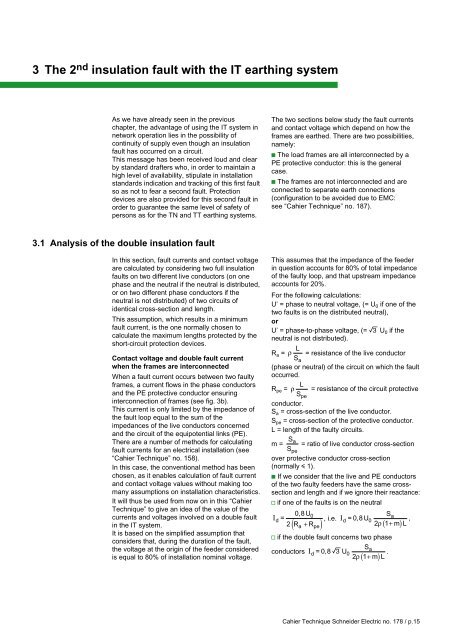
3 <strong>The</strong> 2 nd <strong>in</strong>sulation fault with the <strong>IT</strong> <strong>earth<strong>in</strong>g</strong> <strong>system</strong>As we have already seen <strong>in</strong> the previouschapter, the advantage of us<strong>in</strong>g the <strong>IT</strong> <strong>system</strong> <strong>in</strong>network operation lies <strong>in</strong> the possibility ofcont<strong>in</strong>uity of supply even though an <strong>in</strong>sulationfault has occurred on a circuit.This message has been received loud and clearby standard drafters who, <strong>in</strong> order to ma<strong>in</strong>ta<strong>in</strong> ahigh level of availability, stipulate <strong>in</strong> <strong>in</strong>stallationstandards <strong>in</strong>dication and track<strong>in</strong>g of this first faultso as not to fear a second fault. Protectiondevices are also provided for this second fault <strong>in</strong>order to guarantee the same level of safety ofpersons as for the TN and TT <strong>earth<strong>in</strong>g</strong> <strong>system</strong>s.<strong>The</strong> two sections below study the fault currentsand contact voltage which depend on how theframes are earthed. <strong>The</strong>re are two possibilities,namely:c <strong>The</strong> load frames are all <strong>in</strong>terconnected by aPE protective conductor: this is the generalcase.c <strong>The</strong> frames are not <strong>in</strong>terconnected and areconnected to separate earth connections(configuration to be avoided due to EMC:see “Cahier Technique” no. 187).3.1 Analysis of the double <strong>in</strong>sulation faultIn this section, fault currents and contact voltageare calculated by consider<strong>in</strong>g two full <strong>in</strong>sulationfaults on two different live conductors (on onephase and the neutral if the neutral is distributed,or on two different phase conductors if theneutral is not distributed) of two circuits ofidentical cross-section and length.This assumption, which results <strong>in</strong> a m<strong>in</strong>imumfault current, is the one normally chosen tocalculate the maximum lengths protected by theshort-circuit protection devices.Contact voltage and double fault currentwhen the frames are <strong>in</strong>terconnectedWhen a fault current occurs between two faultyframes, a current flows <strong>in</strong> the phase conductorsand the PE protective conductor ensur<strong>in</strong>g<strong>in</strong>terconnection of frames (see fig. 3b).This current is only limited by the impedance ofthe fault loop equal to the sum of theimpedances of the live conductors concernedand the circuit of the equipotential l<strong>in</strong>ks (PE).<strong>The</strong>re are a number of methods for calculat<strong>in</strong>gfault currents for an electrical <strong>in</strong>stallation (see“Cahier Technique” no. 158).In this case, the conventional method has beenchosen, as it enables calculation of fault currentand contact voltage values without mak<strong>in</strong>g toomany assumptions on <strong>in</strong>stallation characteristics.It will thus be used from now on <strong>in</strong> this “CahierTechnique” to give an idea of the value of thecurrents and voltages <strong>in</strong>volved on a double fault<strong>in</strong> the <strong>IT</strong> <strong>system</strong>.It is based on the simplified assumption thatconsiders that, dur<strong>in</strong>g the duration of the fault,the voltage at the orig<strong>in</strong> of the feeder consideredis equal to 80% of <strong>in</strong>stallation nom<strong>in</strong>al voltage.This assumes that the impedance of the feeder<strong>in</strong> question accounts for 80% of total impedanceof the faulty loop, and that upstream impedanceaccounts for 20%.For the follow<strong>in</strong>g calculations:U’ = phase to neutral voltage, (= U 0 if one of thetwo faults is on the distributed neutral),orU’ = phase-to-phase voltage, (= e U 0 if theneutral is not distributed).R a = ρ L = resistance of the live conductorS a(phase or neutral) of the circuit on which the faultoccurred.R pe = ρ L = resistance of the circuit protectiveS peconductor.S a = cross-section of the live conductor.S pe = cross-section of the protective conductor.L = length of the faulty circuits.m = Sa= ratio of live conductor cross-sectionSpeover protective conductor cross-section(normally i 1).c If we consider that the live and PE conductorsof the two faulty feeders have the same crosssectionand length and if we ignore their reactance:v if one of the faults is on the neutral0,8 UI0Sd =, i.e. Ia2R ( a + R pe )d =0,8U 02ρ ( 1+mL ),v if the double fault concerns two phaseSconductors Iad =0,8eU0 .2 ρ 1 + mL( )Cahier Technique Schneider Electric no. 178 / p.15


