

The IT earthing system (unearthed neutral) in LV
The IT earthing system (unearthed neutral) in LV
The IT earthing system (unearthed neutral) in LV

Create successful ePaper yourself
Turn your PDF publications into a flip-book with our unique Google optimized e-Paper software.
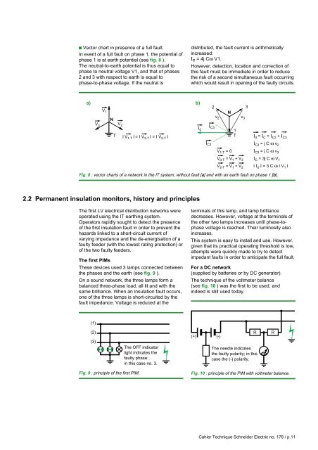
c Vector chart <strong>in</strong> presence of a full faultIn event of a full fault on phase 1, the potential ofphase 1 is at earth potential (see fig. 8 ).<strong>The</strong> neutral-to-earth potential is thus equal tophase to neutral voltage V1, and that of phases2 and 3 with respect to earth is equal tophase-to-phase voltage. If the neutral isdistributed, the fault current is arithmetically<strong>in</strong>creased:I C = 4j Cω V1.However, detection, location and correction ofthis fault must be immediate <strong>in</strong> order to reducethe risk of a second simultaneous fault occurr<strong>in</strong>gwhich would result <strong>in</strong> open<strong>in</strong>g of the faulty circuits.a) b)23V 1NvN2v 3V 3 V 2II C3 d1T I V 1-T I = I V 3-T I = I V 2-T I TI C2V 1-T = 0V 3-T = V 1 + V 3V 2-T = V 1 + V 2I d = I C = I C2 + I C3I C2 = j C ω v 2I C3 = j C ω v 3I C = 3j C ω V 1I I d I = 3 C ω I V 1 IFig. 8 : vector charts of a network <strong>in</strong> the <strong>IT</strong> <strong>system</strong>, without fault [a] and with an earth fault on phase 1 [b].2.2 Permanent <strong>in</strong>sulation monitors, history and pr<strong>in</strong>ciples<strong>The</strong> first <strong>LV</strong> electrical distribution networks wereoperated us<strong>in</strong>g the <strong>IT</strong> <strong>earth<strong>in</strong>g</strong> <strong>system</strong>.Operators rapidly sought to detect the presenceof the first <strong>in</strong>sulation fault <strong>in</strong> order to prevent thehazards l<strong>in</strong>ked to a short-circuit current ofvary<strong>in</strong>g impedance and the de-energisation of afaulty feeder (with the lowest rat<strong>in</strong>g protection) orof the two faulty feeders.<strong>The</strong> first PIMs<strong>The</strong>se devices used 3 lamps connected betweenthe phases and the earth (see fig. 9 ).On a sound network, the three lamps form abalanced three-phase load, all lit and with thesame brilliance. When an <strong>in</strong>sulation fault occurs,one of the three lamps is short-circuited by thefault impedance. Voltage is reduced at theterm<strong>in</strong>als of this lamp, and lamp brilliancedecreases. However, voltage at the term<strong>in</strong>als ofthe other two lamps <strong>in</strong>creases until phase-tophasevoltage is reached. <strong>The</strong>ir lum<strong>in</strong>osity also<strong>in</strong>creases.This <strong>system</strong> is easy to <strong>in</strong>stall and use. However,given that its practical operat<strong>in</strong>g threshold is low,attempts were quickly made to try to detectimpedant faults <strong>in</strong> order to anticipate the full fault.For a DC network(supplied by batteries or by DC generator).<strong>The</strong> technique of the voltmeter balance(see fig. 10 ) was the first to be used, and<strong>in</strong>deed is still used today.(1)(2)(3)<strong>The</strong> OFF <strong>in</strong>dicatorlight <strong>in</strong>dicates thefaulty phase:<strong>in</strong> this case no. 3.(+) (-)R<strong>The</strong> needle <strong>in</strong>dicatesthe faulty polarity; <strong>in</strong> thiscase the (-) polarity.RFig. 9 : pr<strong>in</strong>ciple of the first PIM.Fig. 10 : pr<strong>in</strong>ciple of the PIM with voltmeter balance.Cahier Technique Schneider Electric no. 178 / p.11


