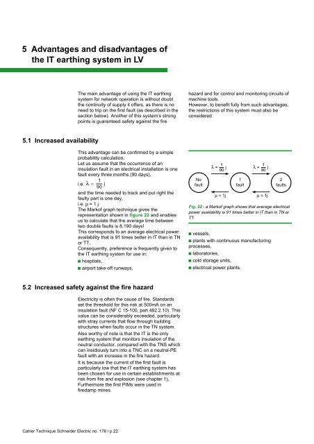
5 Advantages and disadvantages ofthe <strong>IT</strong> <strong>earth<strong>in</strong>g</strong> <strong>system</strong> <strong>in</strong> <strong>LV</strong><strong>The</strong> ma<strong>in</strong> advantage of us<strong>in</strong>g the <strong>IT</strong> <strong>earth<strong>in</strong>g</strong><strong>system</strong> for network operation is without doubtthe cont<strong>in</strong>uity of supply it offers, as there is noneed to trip on the first fault (as described <strong>in</strong> thesection below). Another of this <strong>system</strong>’s strongpo<strong>in</strong>ts is guaranteed safety aga<strong>in</strong>st the firehazard and for control and monitor<strong>in</strong>g circuits ofmach<strong>in</strong>e tools.However, to benefit fully from such advantages,the restrictions of this <strong>system</strong> must also beconsidered.5.1 Increased availabilityThis advantage can be confirmed by a simpleprobability calculation.Let us assume that the occurrence of an<strong>in</strong>sulation fault <strong>in</strong> an electrical <strong>in</strong>stallation is onefault every three months (90 days),1i.e. λ =90 jand the time needed to track and put right thefaulty part is one day,i.e. µ =1j.<strong>The</strong> Markof graph technique gives therepresentation shown <strong>in</strong> figure 22 and enablesus to calculate that the average time betweentwo double faults is 8,190 days!This corresponds to an average electrical poweravailability that is 91 times better <strong>in</strong> <strong>IT</strong> than <strong>in</strong> TNor TT.Consequently, preference is frequently given tothe <strong>IT</strong> <strong>earth<strong>in</strong>g</strong> <strong>system</strong> for use <strong>in</strong>:c hospitals,c airport take-off runways,Nofaultλ = 1 90 jµ = 1j1faultλ = 1 90 jµ = 1j2faultsFig. 22 : a Markof graph shows that average electricalpower availability is 91 times better <strong>in</strong> <strong>IT</strong> than <strong>in</strong> TN orTT.c vessels,c plants with cont<strong>in</strong>uous manufactur<strong>in</strong>gprocesses,c laboratories,c cold storage units,c electrical power plants.5.2 Increased safety aga<strong>in</strong>st the fire hazardElectricity is often the cause of fire. Standardsset the threshold for this risk at 500mA on an<strong>in</strong>sulation fault (NF C 15-100, part 482.2.10). Thisvalue can be considerably exceeded, particularlywith stray currents that flow through build<strong>in</strong>gstructures when faults occur <strong>in</strong> the TN <strong>system</strong>.Also worthy of note is that the <strong>IT</strong> is the only<strong>earth<strong>in</strong>g</strong> <strong>system</strong> that monitors <strong>in</strong>sulation of theneutral conductor, compared with the TNS whichcan <strong>in</strong>sidiously turn <strong>in</strong>to a TNC on a neutral-PEfault with an <strong>in</strong>crease <strong>in</strong> the fire hazard.It is because the current of the first fault isparticularly low that the <strong>IT</strong> <strong>earth<strong>in</strong>g</strong> <strong>system</strong> hasbeen chosen for use <strong>in</strong> certa<strong>in</strong> establishments atrisk from fire and explosion (see chapter 1).Furthermore the first PIMs were used <strong>in</strong>firedamp m<strong>in</strong>es.Cahier Technique Schneider Electric no. 178 / p.22
5.3 Less downtime on control and monitor<strong>in</strong>g circuits<strong>The</strong> relay diagram illustrated <strong>in</strong> figure 23 withthe TN <strong>earth<strong>in</strong>g</strong> <strong>system</strong> shows three possible<strong>in</strong>sulation faults which, when full, result <strong>in</strong>immediate downtime, whose material andeconomic consequences are rarely negligible.<strong>The</strong>se faults have the same consequences withthe TT <strong>system</strong>.In particular, faults c and d cause tripp<strong>in</strong>g of themaster protection device, and prevent allsubsequent operations, such as for example theorder to change direction on a transporter bridge!<strong>The</strong>se same first faults which can causeoperat<strong>in</strong>g malfunctions or even accidents withthe TN and TT <strong>system</strong>s, have no effect with the<strong>IT</strong> <strong>system</strong>, except if they occur as the secondfault (extremely unlikely, see section 5.1).<strong>The</strong>se examples show that even if safety ofpersons with respect to the electrical hazard isguaranteed by the various <strong>earth<strong>in</strong>g</strong> <strong>system</strong>s, orby use of Safety by Extra Low Voltage (SE<strong>LV</strong>),safety of persons with respect to mechanicalhazards may not be guaranteed <strong>in</strong> certa<strong>in</strong> cases.More care must therefore be taken when wir<strong>in</strong>gsuch circuits <strong>in</strong> the TT and TN than <strong>in</strong> the <strong>IT</strong><strong>system</strong>, as the latter warns the operator of the<strong>in</strong>cident (first <strong>in</strong>sulation fault), thereby guard<strong>in</strong>gaga<strong>in</strong>st electrical and mechanical hazards. PIMsare <strong>in</strong>creas<strong>in</strong>gly used for just this purpose, tomonitor automation networks.An additional solution is often advisable,particularly with relays us<strong>in</strong>g electronic devicessensitive to electromagnetic disturbances. <strong>The</strong>aim is to supply all the control and monitor<strong>in</strong>gcircuits separately by means of a <strong>LV</strong>/<strong>LV</strong>transformer with separate w<strong>in</strong>d<strong>in</strong>gs.Despite this, as stated <strong>in</strong> chapter 2, use of the <strong>IT</strong><strong>earth<strong>in</strong>g</strong> <strong>system</strong> has its limits which aredescribed <strong>in</strong> the section below.32N1NPEI dAMR a b c dBFault a cannot be detected.Fault b prevents the off function.Faults c and d cause ashort-circuit.Ma b c dFault a cannot be detected.Faults b, c and d cause ashort-circuit.AFig. 23 : monitor<strong>in</strong>g circuit may be concerned by several types of <strong>in</strong>sulation faults always result<strong>in</strong>g <strong>in</strong> downtimewith TT and TN <strong>system</strong>.5.4 Restrictions and precautions for us<strong>in</strong>g the <strong>IT</strong> <strong>earth<strong>in</strong>g</strong> <strong>system</strong><strong>The</strong> restrictions for us<strong>in</strong>g the <strong>IT</strong> <strong>system</strong> arel<strong>in</strong>ked to loads and networks.Limits l<strong>in</strong>ked to loadsc With a high earth capacitive coupl<strong>in</strong>g(presence of filters).A number of devices fitted with capacitive filters(see fig. 24 ) offer the same disadvantage, dueto their number, as very long networks when the<strong>IT</strong> <strong>system</strong> is used.<strong>The</strong>se capacitive leakages have a particularity,with respect to distributed capacity ma<strong>in</strong>ly due tonetwork cables, i.e. they can be unbalanced.DeviceMicro-computerUPSVariable speed controlersFluorescent tubes(<strong>in</strong> ramps of 10)Network/earth capacity20 nF to 40 nF40 nF70 nF20 nFFig. 24 : guidel<strong>in</strong>e capacitive values for HF filters built<strong>in</strong>to various devices.Cahier Technique Schneider Electric no. 178 / p.23