- Page 1:
NIST Technical Note 1455Performance
- Page 4 and 5:
Certain commercial entities, equipm
- Page 8 and 9:
2.5 Alarm Identification ..........
- Page 10 and 11:
7.5.3 Tell-tale Sprinklers ........
- Page 12 and 13:
Figure 37. Ion-1, six wicks 12 s de
- Page 14 and 15:
Figure 106. Gas temperatures from c
- Page 16 and 17:
Figure 161. Frying margarine scenar
- Page 18 and 19:
Figure 205. Bread in a toaster, fan
- Page 20 and 21:
xviii
- Page 22 and 23:
The fire emulator/detector evaluato
- Page 24 and 25:
installed close to cooking applianc
- Page 26 and 27:
xxiv
- Page 28 and 29:
Canada (NRCC), in conjunction with
- Page 30 and 31:
NIST, and others felt that it was t
- Page 32 and 33:
A second test site, obtained throug
- Page 34 and 35:
Thus typical residential sprinklers
- Page 37 and 38:
2 Residential Fire Alarms, Sensor R
- Page 39 and 40:
Figure 2. Schematic of the FE/DE (a
- Page 41 and 42:
urner fuel and air wereincremented
- Page 43 and 44:
Thus, within the range typical ofio
- Page 45 and 46:
k = ln( I / I ) L mextinction (m -1
- Page 47 and 48:
The test series are identified as S
- Page 49 and 50:
Detector Test Series a bm 0bm 1 R c
- Page 51 and 52:
87Obscuration (%/ft)654321Smolder s
- Page 53 and 54:
87Obscuration (%/ft)654321Smolder s
- Page 55 and 56:
Table 2. Listed unmodified alarm se
- Page 57 and 58:
1Laser Light Transmittance(1.52 m p
- Page 59 and 60:
1Laser Light Transmittance(1.52 m p
- Page 61 and 62:
Figures 28 - 37 show the results fo
- Page 63 and 64:
1Laser Light Transmittance(1.52 m p
- Page 65 and 66:
1Laser Light Transmittance(1.52 m p
- Page 67 and 68:
Laser Light Transmittance(1.52 m pa
- Page 69 and 70:
Laser Light Transmittance(1.52 m pa
- Page 71 and 72:
Laser Light Transmittance(1.52 m pa
- Page 73 and 74:
2.7 Effect of Sensor Board Location
- Page 75 and 76:
0.3Axial velocity 5 cm below ceilin
- Page 77 and 78:
0.7-5Laser Light Transmittance(1.52
- Page 79 and 80:
0.4-4Laser Light Transmittance(1.52
- Page 81 and 82:
0.5-5Laser Light Transmittance(1.52
- Page 83 and 84:
0.71Laser Light Transmittance(1.52m
- Page 85 and 86:
0.41Laser Light Transmittance(1.52m
- Page 87 and 88:
0.51Laser Light Transmittance(1.52m
- Page 89:
for all (modified) ionization alarm
- Page 92 and 93:
Table 6. Top fire scenarios ranked
- Page 94 and 95:
The flaming chair was chosen with a
- Page 96 and 97:
3.3 Ignition MethodologyThere were
- Page 98 and 99:
Figure 85 shows the smoldering rod
- Page 100 and 101:
20.12 m4.06 m2.34 m 1.68 m 2.59 m74
- Page 102 and 103:
3.34 m2.29 m 3.27 m0.53 mBath3.63 m
- Page 104 and 105:
temperature measurement in the diff
- Page 106 and 107:
1.04 m0.53 m0.80 m3.38 mTemperature
- Page 108 and 109:
4.2 Sample MassMass loss from the o
- Page 110 and 111:
With different line lengths, vacuum
- Page 112 and 113:
Table 9. Locations for primary opti
- Page 114 and 115:
Finally, a size distribution measur
- Page 116 and 117:
of the limited supply of analog-mod
- Page 119 and 120:
5 Fire Source Test Results and Calc
- Page 121 and 122:
Table 12. Test Conditions for tests
- Page 123 and 124:
Remote Bedroom45Temperature (°C)40
- Page 125 and 126:
Hallway Outside Remote Bedroom70Tem
- Page 127 and 128: Living Room60Temperature (°C)50403
- Page 129 and 130: Closed Bedroom301520 mm25Temperatur
- Page 131 and 132: Remote Bedroom2.52.020 mm900 mmOpti
- Page 133 and 134: Hallway Outside Remote Bedroom1.41.
- Page 135 and 136: Living Room2.52.020 mm900 mmOptical
- Page 137 and 138: Closed Bedroom0.10Initiation of Sup
- Page 139 and 140: Carbon Dioxide2.01.5Remote BedroomM
- Page 141 and 142: Smoke Alarm Output10030Smoke Alarm
- Page 143 and 144: Heat Alarm-600Initiation of Suppres
- Page 145 and 146: • carbon monoxide alarms - 50 x 1
- Page 147 and 148: 5.4.2 Tenability TimesChapter 8 of
- Page 149 and 150: Alarm Code was revised to require s
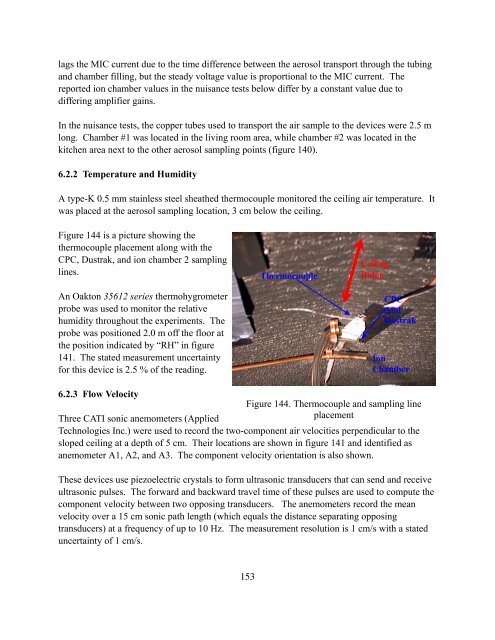
- Page 151 and 152: Measurements of the aerosol number
- Page 153 and 154: ANumber Concentration (particles/cm
- Page 155 and 156: Number Concentration (particles/cm3
- Page 157 and 158: ANumber Concentration (particles/cm
- Page 159 and 160: ANumber Concentration (particles/cm
- Page 161 and 162: 10 6 Number0.8Ion 110 5Ion 2Ion 3Io
- Page 163 and 164: SDC24 was a cooking oil fire in the
- Page 165 and 166: 5002Mass Concentration (mg/m3)37525
- Page 167 and 168: Table 17. Cascade impactor resultsT
- Page 169 and 170: 50 % cut-off Diameter(μm)1010.1MMA
- Page 171 and 172: 50 % cut-off Diameter(μm)1010.1MMA
- Page 173 and 174: Table 19. Estimated particle size f
- Page 175 and 176: 6 Residential Smoke Alarm Nuisance
- Page 177: A2ARHCBA1DEA3FGU+V+Figure 141. Sche
- Page 181 and 182: On several occasions, the SBC data
- Page 183 and 184: 0.50.5Velocity or Speed (m/s)0.250-
- Page 185 and 186: One can still observe trends in the
- Page 187 and 188: Time to Alarm Threshold (s)A6005004
- Page 189 and 190: Time to Alarm Threshold (s)A4003503
- Page 191 and 192: • Photoelectric alarm thresholds
- Page 193 and 194: trend and both experience two peak
- Page 195 and 196: Figure 156 shows the results for ba
- Page 197 and 198: Time to Alarm Threshold (s)A6005004
- Page 199 and 200: Time to Alarm Threshold (s)A4003002
- Page 201 and 202: Figure 161 shows the results for ma
- Page 203 and 204: ose about 2 %. The mass concentrati
- Page 205 and 206: Time to Alarm Threshold (s)A7006005
- Page 207 and 208: photoelectric alarms; however one c
- Page 209 and 210: 6.3.6 Broiled and Baked/Broiled Piz
- Page 211 and 212: Time to Alarm Threshold (s)A1300120
- Page 213 and 214: 6.3.7 Broiling HamburgersFour 110 g
- Page 215 and 216: Time to Alarm Threshold (s)A1000800
- Page 217 and 218: Time to Alarm Threshold (s)A6005004
- Page 219 and 220: 6.3.9 Candle BurningFour scented te
- Page 221 and 222: Time to Alarm Threshold (s)A1008060
- Page 223 and 224: ealizing the early peak, then climb
- Page 225 and 226: • A somewhat counterintuitive obs
- Page 227 and 228: Time to Alarm Threshold (s)A1300120
- Page 229 and 230:
Time to Alarm Threshold (s)A8006004
- Page 231 and 232:
Time to Alarm Threshold (s)A8007006
- Page 233 and 234:
6.5 FE/DE Emulation of Nuisance Sou
- Page 235 and 236:
10080MICD1D86050MIC Current (pA)604
- Page 237 and 238:
6.5.2 Cotton Smolder Smoke Fire Sce
- Page 239 and 240:
0.50.4ExtinctionMIC1008010080MICD1D
- Page 241 and 242:
0.250.2ExtinctionMIC1008010080MICD1
- Page 243 and 244:
0.80.70.6ExtinctionMIC1008010080MIC
- Page 245 and 246:
0.50.4ExtinctionMIC100908010080MICD
- Page 247 and 248:
6.5.5 Heated Margarine or Butter Nu
- Page 249 and 250:
Extinction (m -1 )A0.0350.030.0250.
- Page 251 and 252:
21.5ExtinctionMIC1008010080MICD1D86
- Page 253 and 254:
21.5ExtinctionMIC1008010080MICD1D86
- Page 255 and 256:
2.521008010080MICD1D86050Extinction
- Page 257 and 258:
7 DiscussionIn 1975, the Indiana Du
- Page 259 and 260:
one of the Dual Ion/Photo alarms in
- Page 261 and 262:
Table 24. Average time to alarm (in
- Page 263 and 264:
series of actions beginning with cu
- Page 265 and 266:
Distances are taken as straight lin
- Page 267 and 268:
On average, the photoelectric alarm
- Page 269 and 270:
Table 28. Available egress time (in
- Page 271 and 272:
800700600PhotoIonDual Ion/PhotoAspi
- Page 273 and 274:
protection against injury, life los
- Page 275 and 276:
ate of fire growth (table 32). Aver
- Page 277 and 278:
The FE/DE nuisance source tests cap
- Page 279 and 280:
8 SummaryThe data developed in this
- Page 281 and 282:
4. Develop standard nuisance alarm
- Page 283 and 284:
Finally, a press day was held that
- Page 285 and 286:
9 Conclusions1. The data developed
- Page 287 and 288:
10 References[1] Bukowski, R. W., W
- Page 289 and 290:
[23] The SFPE Handbook of Fire Prot
- Page 291 and 292:
[48] Bryan, J. L. “Project People
- Page 293 and 294:
Calculated Alarm Times
- Page 295 and 296:
1 2 3 4 5 6 7 8 9 10 11 12 13 14 15
- Page 297 and 298:
Test SDC03 Smoldering Mattress in B
- Page 299 and 300:
Test SDC05 Flaming Mattress in Bedr
- Page 301 and 302:
Test SDC07 Flaming Mattress in Bedr
- Page 303 and 304:
Test SDC09 Flaming Mattress in Bedr
- Page 305 and 306:
Test SDC11 Smoldering Chair in Livi
- Page 307 and 308:
Test SDC13 Vegetable Oil on Kitchen
- Page 309 and 310:
Test SDC15 Flaming Chair Living Roo
- Page 311 and 312:
Test SDC21 Smoldering Mattress in B
- Page 313 and 314:
Test SDC23 Smoldering Chair in Livi
- Page 315 and 316:
Test SDC25 Flaming Chair in Living
- Page 317 and 318:
Test SDC27 Smoldering Chair in Livi
- Page 319 and 320:
Series ..\Manufactured Home Series
- Page 321 and 322:
Test SDC32 Flaming Chair in Living
- Page 323 and 324:
Test SDC35 Flaming Chair in Living
- Page 325 and 326:
Test SDC37 Smoldering Mattress in B
- Page 327 and 328:
Test SDC39 Flaming Mattress in Bedr
- Page 329 and 330:
Test SDC41 Vegetable Oil on Kitchen
- Page 331 and 332:
12345678910111213141516171819202122
- Page 333 and 334:
81828384858687888990919293949596979
- Page 335 and 336:
15715815916016116216316416516616716
- Page 337 and 338:
23323423523623723823924024124224324
- Page 339 and 340:
30730830931031131231331431531631731
- Page 341 and 342:
38138238338438538638738838939039139
- Page 343 and 344:
45645745845946046146246346446546646
- Page 345 and 346:
52752852953053153253353453553653753
- Page 347 and 348:
60260360460560660760860961061161261
- Page 349 and 350:
67867968068168268368468568668768868
- Page 351 and 352:
75475575675775875976076176276376476
- Page 353 and 354:
83083183283383483583683783883984084
- Page 355 and 356:
90690790890991091191291391491591691
- Page 357 and 358:
98298398498598698798898999099199299
- Page 359 and 360:
10661067106810691070107110721073107
- Page 361 and 362:
11541155115611571158115911601161116
- Page 363 and 364:
12421243124412451246124712481249125
- Page 365 and 366:
13301331133213331334133513361337133
- Page 367 and 368:
Appendix BFTIR Gas Measurement in H
- Page 369 and 370:
FTIR GAS MEASUREMENT IN HOME SMOKE
- Page 371 and 372:
Figure 16. Average of spectra for t
- Page 373 and 374:
2.0 EXPERIMENTSExperimental details
- Page 375 and 376:
Figure 1. Manufactured home and FTI
- Page 377 and 378:
Figure 3. Upholstered chairs before
- Page 379 and 380:
3.0 RESULTS AND DISCUSSIONA total o
- Page 381 and 382:
and 500°C in Test 7. Figure 19 sho
- Page 383 and 384:
.05.04Absorbance.03.02CO2CO2.010H2O
- Page 385 and 386:
.05.04Absorbance.03.02H2OH2O.01CO20
- Page 387 and 388:
.2CO2CO2.15Absorbance.1.05H2OH2O0CO
- Page 389 and 390:
.1.08.050Absorbance.06.04CO2-.05720
- Page 391 and 392:
.14.12.1CO2CO2Absorbance.08.06.04.0
- Page 393 and 394:
1.41.2NDIRFTIR1.00.8CO 2[%]0.60.40.
- Page 395 and 396:
0.050.04NDIRFTIR0.03CO [%]0.020.010