Liebert Mini-Mate2, 8 Ton - Emerson Network Power
Liebert Mini-Mate2, 8 Ton - Emerson Network Power
Liebert Mini-Mate2, 8 Ton - Emerson Network Power

You also want an ePaper? Increase the reach of your titles
YUMPU automatically turns print PDFs into web optimized ePapers that Google loves.
2.5.3 Piping Connections<br />
20<br />
Site Preparation and Installation<br />
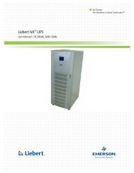
Details for refrigerant (R-22) loop piping are in 2.4.3 - Piping Connections and Coolant Requirements.<br />
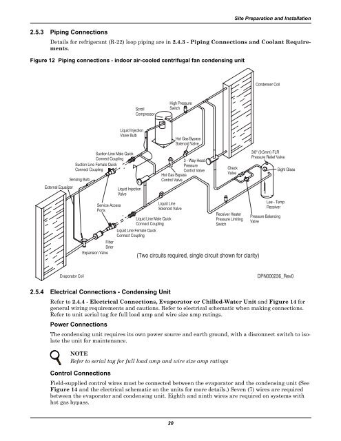
Figure 12 Piping connections - indoor air-cooled centrifugal fan condensing unit<br />
External Equalizer<br />
2.5.4 Electrical Connections - Condensing Unit<br />
Refer to 2.4.4 - Electrical Connections, Evaporator or Chilled-Water Unit and Figure 14 for<br />
general wiring requirements and cautions. Refer to electrical schematic when making connections.<br />
Refer to unit serial tag for full load amp and wire size amp ratings.<br />
<strong>Power</strong> Connections<br />
The condensing unit requires its own power source and earth ground, with a disconnect switch to isolate<br />
the unit for maintenance.<br />
NOTE<br />
Refer to serial tag for full load amp and wire size amp ratings<br />
Control Connections<br />
Liquid Injection<br />
Valve Bulb<br />
Suction Line Male Quick<br />
Connect Coupling<br />
Suction Line Female Quick<br />
Connect Coupling<br />
*<br />
Sensing Bulb<br />
Evaporator Coil<br />
Service Access<br />
Ports<br />
Liquid Injection<br />
Valve<br />
Scroll<br />
Compressor<br />
High Pressure<br />
Switch<br />
Hot Gas Bypass<br />
Control Valve<br />
Liquid Line<br />
Solenoid Valve<br />
*<br />
Liquid Line Male Quick<br />
Connect Coupling<br />
Liquid Line Female Quick<br />
Connect Coupling<br />
Filter<br />
Drier<br />
Expansion Valve<br />
Hot Gas Bypass<br />
Solenoid Valve<br />
3 - Way Head<br />
Pressure<br />
Control Valve<br />
Condenser Coil<br />
Field-supplied control wires must be connected between the evaporator and the condensing unit (See<br />
Figure 14 and the electrical schematic on the units for more details.) Seven (7) wires are required<br />
between the evaporator and condensing unit. Eighth and ninth wires are required on systems with<br />
hot gas bypass.<br />
Check<br />
Valve<br />
Receiver Heater<br />
Pressure Limiting<br />
Switch<br />
(Two circuits required, single circuit shown for clarity)<br />
3/8" (9.5mm) FLR<br />
Pressure Relief Valve<br />
Lee - Temp<br />
Receiver<br />
Pressure Balancing<br />
Valve<br />
Sight Glass<br />
DPN000236_Rev0