Liebert Mini-Mate2, 8 Ton - Emerson Network Power
Liebert Mini-Mate2, 8 Ton - Emerson Network Power
Liebert Mini-Mate2, 8 Ton - Emerson Network Power

Create successful ePaper yourself
Turn your PDF publications into a flip-book with our unique Google optimized e-Paper software.
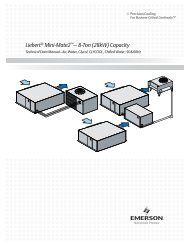
2.6 Outdoor Air-Cooled Condensing Unit Installation<br />
2.6.1 Location Considerations<br />
23<br />
Site Preparation and Installation<br />
To insure a satisfactory air supply, locate air-cooled propeller fan condensing units in an environment<br />
providing clean air, away from loose dirt and foreign matter that may clog the coil. Condensing units<br />
must not be located in the vicinity of steam, hot air, or fume exhausts, or closer than 18 inches from a<br />
wall, obstruction, or adjacent unit. Avoid areas where heavy snow will accumulate at air inlet and discharge<br />
locations.<br />
The condensing unit should be located for maximum security and maintenance accessibility. Avoid<br />
ground-level sites with public access.<br />
Install a solid base, capable of supporting the weight of the condensing unit. The base should be at<br />
least 2 inches higher than the surrounding grade and 2 inches larger than the dimensions of the condensing<br />
unit base. For snowy areas, a base of sufficient height to clear snow accumulation must be<br />
installed.<br />
2.6.2 Piping Connections<br />
Details for refrigerant (R-22) loop piping are in Figure 12 - Piping connections - indoor aircooled<br />
centrifugal fan condensing unit.<br />
2.6.3 Electrical Connections<br />
Refer to 2.4.4 - Electrical Connections, Evaporator or Chilled-Water Unit for general wiring<br />
requirements and cautions. Refer to electrical schematic when making connections.<br />
<strong>Power</strong> Connections<br />
The outdoor condensing unit requires its own power source and earth ground, with a disconnect<br />
switch (field supplied) to isolate the unit for maintenance.<br />
Control Connections<br />
Field-supplied control wires must be connected between the evaporator and the condensing unit. (See<br />
Figure 6 and the electrical schematic on the units for more details.) Seven (7) wires are required<br />
between the evaporator and condensing unit. Eighth and ninth wires are required on systems with<br />
hot gas bypass.