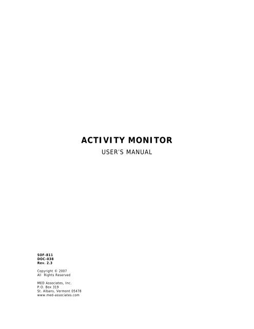
ACTIVITY MONITOR - Vanderbilt Kennedy Center
ACTIVITY MONITOR - Vanderbilt Kennedy Center
ACTIVITY MONITOR - Vanderbilt Kennedy Center

You also want an ePaper? Increase the reach of your titles
YUMPU automatically turns print PDFs into web optimized ePapers that Google loves.
SOF-811<br />
DOC-038<br />
Rev. 2.3<br />
Copyright © 2007<br />
All Rights Reserved<br />
MED Associates, Inc.<br />
P.O. Box 319<br />
St. Albans, Vermont 05478<br />
www.med-associates.com<br />
<strong>ACTIVITY</strong> <strong>MONITOR</strong><br />
USER’S MANUAL
MED ASSOCIATES INC. <strong>ACTIVITY</strong> <strong>MONITOR</strong><br />
- ii -
MED ASSOCIATES INC. <strong>ACTIVITY</strong> <strong>MONITOR</strong><br />
TABLE OF CONTENTS<br />
Chapter 1 ........................................................................................................ 1<br />
General Information ...........................................................................................1<br />
General Computer Environment.........................................................................1<br />
Installing the DIG-729 Interface Card ................................................................1<br />
Installing the Activity Monitor Drivers and Software .............................................1<br />
Backing Up Software .......................................................................................2<br />
Connecting the Activity Chambers......................................................................2<br />
Modifying I/R Array Height ...............................................................................4<br />
Chapter 2 ........................................................................................................ 5<br />
Getting Started..................................................................................................5<br />
General Software Information ...........................................................................5<br />
Introduction to Open-Field Activity Monitoring.....................................................5<br />
Chapter 3 ........................................................................................................ 8<br />
Menu Options....................................................................................................8<br />
File Menu Options ...........................................................................................8<br />
View Menu Options........................................................................................ 19<br />
Run Menu Options......................................................................................... 20<br />
Window Menu Options ................................................................................... 27<br />
Help Menu Options........................................................................................ 27<br />
Chapter 4 ...................................................................................................... 28<br />
Data Analysis Menu Options .............................................................................. 28<br />
Data Analysis Setup....................................................................................... 28<br />
General Analysis Information .......................................................................... 30<br />
Zone Analysis ............................................................................................... 32<br />
Rotational Behavior Calculations...................................................................... 34<br />
Using the Rotational Analysis Utility................................................................. 37<br />
Save/Load Protocol ....................................................................................... 37<br />
Chapter 5 ...................................................................................................... 39<br />
Inserts for Open-Field Activity ........................................................................... 39<br />
Dark Box Insert (Light/Dark Test).................................................................... 39<br />
Two Chamber Place Preference ....................................................................... 40<br />
Hole Board Task Floor.................................................................................... 40<br />
- iii -
MED ASSOCIATES INC. <strong>ACTIVITY</strong> <strong>MONITOR</strong><br />
Chapter 6 ...................................................................................................... 41<br />
Setting up an Ambulatory Experiment ................................................................. 41<br />
Chapter 7 ...................................................................................................... 50<br />
Setting up a Hole Board Experiment ................................................................... 50<br />
Appendix I .................................................................................................... 57<br />
File Naming and File Types................................................................................ 57<br />
File Naming.................................................................................................. 57<br />
File Types .................................................................................................... 57<br />
Appendix II ................................................................................................... 59<br />
Available Data ................................................................................................. 59<br />
Summary Data.............................................................................................. 59<br />
Analyzed Data .............................................................................................. 62<br />
Hole Board Task Data .................................................................................... 69<br />
Exported Raw Data Files ................................................................................ 72<br />
Appendix III.................................................................................................. 74<br />
Importing Data Using MDB to Excel .................................................................... 74<br />
Appendix IV .................................................................................................. 78<br />
Using Box Size, Resting Delay, Include Resting Delay, and Ambulatory Trigger ......... 78<br />
Defining Distance Traveled ............................................................................. 78<br />
Differentiating Between Large/Quick and Small/Slow Movements ......................... 79<br />
Appendix V .................................................................................................... 81<br />
Multiple Users ................................................................................................. 81<br />
Appendix VI .................................................................................................. 83<br />
ENV-520 Jumper Positions for Nodes 1-16 (Chambers 1-8)..................................... 83<br />
Appendix VII ................................................................................................. 84<br />
Hole Board Protocols ........................................................................................ 84<br />
Non-Habituation Protocol ............................................................................... 84<br />
Habituation Protocol ...................................................................................... 84<br />
Appendix VIII ............................................................................................... 85<br />
Start on Remote Start Command ........................................................................ 85<br />
Appendix IX .................................................................................................. 87<br />
DIG-729 ISA Card ............................................................................................ 87<br />
- iv -
MED ASSOCIATES INC. <strong>ACTIVITY</strong> <strong>MONITOR</strong><br />
CHAPTER 1<br />
General Information<br />
General Computer Environment<br />
The minimum recommended system is as follows:<br />
• 800 MHz or faster computer with at least one free ISA or PCI slot, or one USB port.<br />
• Windows 98, 2000, or XP<br />
• 256 MB of RAM (512MB of RAM if running Windows 2000 or XP)<br />
• 1 GB of free disk space<br />
• CD-Rom drive<br />
• Mouse<br />
Installing the DIG-729 Interface Card<br />
Always turn off the power before working on the computer or chambers. Neglecting this<br />
precaution may cause serious damage. If a DIG-729 PCI card is being used, install the<br />
DIG-729 card according to the instructions provided with the computer for installing a<br />
PCI card.<br />
Installing the Activity Monitor Drivers and Software<br />
Prior to installing the software, the necessary drivers must be installed on the computer.<br />
Insert the Activity Monitor CD into the CD-ROM drive and the screen shown in Figure 1.1<br />
should appear. If it does not, open the CD-ROM drive containing the Activity Monitor CD<br />
and open the file named autorun.exe.<br />
Figure 1-1 - Activity Monitor Main Menu<br />
- 1 -
MED ASSOCIATES INC. <strong>ACTIVITY</strong> <strong>MONITOR</strong><br />
From the screen shown in Figure 1-1, select the type of DIG-729 device being used, then<br />
follow the instructions to install the device drivers. Once all of the necessary drivers<br />
have been installed, select To install Activity Monitor 5 click here.<br />
Backing Up Software<br />
Making a backup copy of any data files created by Activity Monitor (especially the file<br />
DEFAULT.ZIP) is strongly advised.<br />
Connecting the Activity Chambers<br />
Connect the DIG-729 card to the ENV-520 Controller on Chamber #1 using the 15 pin<br />
SG-219C control cable.<br />
NOTE: The chambers numbers are indicated on the ENV-520 Controllers. This number is<br />
factory set with jumpers inside the ENV-520 and should not be modified unless necessary<br />
(Appendix VI).<br />
Figure 1-2 - Activity Chamber Setup<br />
Additional chambers are connected via their ENV-520s controllers with SG-219C control<br />
cables, starting at Chamber #1 and proceeding in sequence, in a daisy chain fashion.<br />
For example, if there are four chambers, Chamber #1 connects to Chamber #2, Chamber<br />
#2 connects to Chamber #3, and finally Chamber #3 connects to Chamber #4. Ensure<br />
each connector is securely attached to the ENV-520 by tightening the screws on the<br />
cable. Connect the power cords from all ENV-520s to the SG-506 power supply. See<br />
Chapter 3 for a quick hardware test utility that can be run to verify proper operation of<br />
all photo beams before actually running an experiment.<br />
MED Associates assembles equipment prior to shipment. The ribbon cables are<br />
connected from the ENV-520 to the I/R Array Strips as shown in Figure 1-2. The<br />
corresponding receiver strips are located directly opposite the transmitter strips.<br />
- 2 -
MED ASSOCIATES INC. <strong>ACTIVITY</strong> <strong>MONITOR</strong><br />
Figure 1-3 - Activity Chamber with Hole Board Insert<br />
• Hole Board Transmitters 1 and 2 connect to the “Transmitter 3” port on the ENV-<br />
520 Controller.<br />
• Hole Board Receivers 1 and 2 connect to the “Receiver 3” port.<br />
• Transmitter 1 gets connected to the “Transmitter 1” port.<br />
• Transmitter 2 gets connected to the “Transmitter 2” port.<br />
• Receiver 1 gets connected to the “Receiver 1” port.<br />
• Receiver 2 gets connected to the “Receiver 2” port.<br />
An easy way to check that the I/R Array Strips are correctly connected is to run a quick<br />
one-minute test experiment. Place an object into the test chamber and confirm that the<br />
red dot on the run-time screen is tracking correctly (i.e., back left in the chamber should<br />
be top left on the screen and front right in the chamber should be bottom right on the<br />
screen).<br />
- 3 -
MED ASSOCIATES INC. <strong>ACTIVITY</strong> <strong>MONITOR</strong><br />
Modifying I/R Array Height<br />
Do not assume that the factory set I/R Array heights are appropriate for the experiments<br />
being run. Different ages and strains of subjects may have vastly different physical<br />
characteristics. Also, because we have developed inserts (Chapter 5) to increase the<br />
system’s functionality, the I/R Array strip heights from the environment floor may need<br />
to be adjusted.<br />
The closer the I/R Array strips are placed toward the subjects' vertical center (for X & Y<br />
arrays), the better the data. If a subject is too low for the I/R strips, or capable of<br />
"crouching" periodically below the strips, the subject may disappear from "sight" of the<br />
system from time to time. The software is designed to remember the last location and<br />
pick back up when the subject becomes "visible" again. Typically, this will have little<br />
bearing on the data; however, if using Velocity data, there could be a sudden increase in<br />
a subjects' velocity and Jump Counts and Time will be affected. There may be other<br />
scenarios whereby inaccurate I/R strip placement may present erroneous data, so use<br />
care in this process.<br />
The "Z" I/R Array strips should be placed in the lowest available position capable of<br />
detecting vertical activity and not detecting normal "X" & "Y" activity. If the strips are<br />
too high, some rearings may not be detected, or slight "bouncing" while rearing may<br />
cause multiple rearings to be detected when only one rearing episode was indeed<br />
elicited.<br />
- 4 -
MED ASSOCIATES INC. <strong>ACTIVITY</strong> <strong>MONITOR</strong><br />
CHAPTER 2<br />
Getting Started<br />
General Software Information<br />
Data analysis has been taken to an entirely new level with the addition of such measures<br />
as rotational behaviors, zone entries, jumping, etc. (Appendix II) added to the system.<br />
Data acquired on systems using Version 3.0 or higher may be reanalyzed in this version<br />
to obtain these new measures. The analysis parameters may be changed and the data<br />
re-analyzed to extract additional information.<br />
The Activity Monitor is designed for use with MED Associates hardware to collect, plot,<br />
and analyze activity data. All standard data is displayed in real-time, along with a<br />
cumulative plot of the subject's activity. The data acquisition configuration files, which<br />
specify the state of the system (Resolution/Sample Rates, Ambulatory/Stereotypic<br />
Movement definitions), are stored in filename.CFG files. The default settings are userdefined<br />
and determined the very first time that the Activity Monitor software is run. See<br />
Chapter 3, for Configuration File set up.<br />
In addition to providing the database to store all experiment and subject data and<br />
information, we have also provided the option to create an ASCII text and a "hard copy"<br />
printed summary data file automatically. After each subjects’ session or after each<br />
experiment (multiple subjects), the software can print the summary data automatically<br />
and save a summary data file for each subject, simply by checking the appropriate check<br />
boxes in the preference settings window (Figure 3-3). Likewise, analyzed data and Raw<br />
Point data ASCII text files may also be generated aside from the database file. All ASCII<br />
text files are named according to the file-naming scheme presented in Table 3-4 and<br />
discussed in Appendix I.<br />
There are two database files created by the Activity Monitor software: EXP.MDB and<br />
ANALYSIS.MDB. These files are Access ® database files, but may be opened with many<br />
database programs. In order to extract precisely formatted data, they must be<br />
manipulated or sorted with a database program that can open a standard Access ®<br />
scheme. We have opted to create this database to enable researchers to export an<br />
entire experiments worth of analyzed data, sorted and defined, into a spreadsheet to<br />
make Subject, Group, and Experiment data analysis simple and fast.<br />
Introduction to Open-Field Activity Monitoring<br />
Open-Field Activity (OFA) monitoring is a sensitive method of measuring both gross and<br />
fine locomotor activity in small animals. In general, computerized OFA characterizes<br />
multiple end points of motor behavior, and has proven to be a powerful assessment tool<br />
with many applications in behavioral pharmacology, toxicology, and genetics. For<br />
example, dopamine agonist studies can use distance traveled in centimeters as a<br />
measure of gross motor activity that is amenable to quantitative analysis. Opiate<br />
tolerance studies can examine overall distance traveled, but can also utilize time and<br />
distance in the margin of the chamber as well. Anxiety can also be characterized with an<br />
- 5 -
MED ASSOCIATES INC. <strong>ACTIVITY</strong> <strong>MONITOR</strong><br />
OFA system using the above mentioned thigmotaxis measure and by examining patterns<br />
of exploration in a brightly lit arena with a dark area (See Dark Box Insert – Light/Dark<br />
Conflict Test). In addition, other models with proven construct validity, such as the hole<br />
board task and place preference, can also be performed with the MED Associates’<br />
System. These add-on components make the MED Associates’ OFA system very versatile<br />
and an excellent value for laboratories that are both space and cost conscience.<br />
Two standard sized environments, the ENV-510, 10.75" X 10.75" X 8" H (27 X 27 X 20.3<br />
cm) and the ENV-515, 17" X 17" X 12" H (43.2 X 43.2 X 30.5 cm) are suitable for mouse<br />
and rat protocols, respectively. The system consists of a subject containment<br />
environment (chamber), infrared (I/R) sources and sensors, a system power supply, an<br />
environment data source controller, appropriate connecting cables, a PC/environment<br />
interface card, and the data acquisition/analysis software. Subject location is tracked<br />
using 16 evenly spaced I/R sources and sensors juxtaposed around the periphery of the<br />
four sides of the chamber. This I/R beam array defines an X and Y coordinate "map" for<br />
the system. The sensors detect the presence or absence of the I/R beam (i.e., the<br />
subject) at these corresponding coordinates.<br />
At user defined time intervals, the software has instructions to “poll” the environment for<br />
the presence or absence of the I/R beam at each sensor. This is the scanning rate or<br />
sampling rate of the system. If the I/R beam fails to reach the sensor, the system<br />
registers this event as a broken beam and assumes the presence of the subject. Broken<br />
beams at X 1,2,3,4 and Y 2,3,4,5 are averaged, with the resulting microprocessor derived<br />
coordinate being X = 2.5 and Y = 3.5 or just 2.5, 3.5. The averaged beam breaks or<br />
subject "centers" are the data that the software algorithms use to derive the behavioral<br />
parameters such as distance traveled and time spent in a given zone. The software thus<br />
has a resolution of 32 x 32.<br />
By scanning or “polling” the environment many times a second, the OFA system can<br />
effectively track the movement of a subject very precisely. The faster the scanning rate,<br />
the greater the accuracy of the system for high speed behavioral measures such as<br />
stereotypic behaviors, as well as for event-related, time-sorted data.<br />
We offer variable scanning rates to accommodate personal preferences (<br />
Table 3-1). Many researchers feel that there are few advantages to faster scanning rates<br />
for long trial runs where the data of interest does not require the increased rates. After<br />
all, faster scanning rates mean larger data files and longer post-hoc data analysis<br />
processing times.<br />
For such researchers, we have designed the software so that measurements may be<br />
taken as small samples, repeated at preset intervals (<br />
Table 3-1). This allows for focused data files and virtually eliminates the need to sort<br />
through large quantities of data to extract the desired measures. Experience in this<br />
matter will help to determine the test type, continuous or segmented, and the scanning<br />
rate that is best for the application.<br />
The addition of a photo beam array above a subject adds a second plane of detection to<br />
the system. This is used to detect the presence or absence of a subject in this plane.<br />
The "Z" coordinate is used to detect rearing or standing on the hind legs.<br />
- 6 -
MED ASSOCIATES INC. <strong>ACTIVITY</strong> <strong>MONITOR</strong><br />
The menu selections are outlined in the next chapter. The above general system and<br />
open-field information will assist with understanding what the menu selections mean and<br />
why they are important.<br />
- 7 -
MED ASSOCIATES INC. <strong>ACTIVITY</strong> <strong>MONITOR</strong><br />
CHAPTER 3<br />
Menu Options<br />
To run the Activity Monitor, select the Activity Monitor program group and double click on<br />
the Activity Monitor icon. The main Activity Monitor screen appears with a copyright<br />
screen that disappears after a few seconds (Figure 3-1).<br />
Figure 3-1 - Activity Monitor Copyright Screen<br />
The main Activity window is now displayed. This window is blank. There is a menu<br />
displayed across the top of the window with all the software functions that are accessible<br />
within this blank window.<br />
File Menu Options<br />
Preferences<br />
Select File | Preferences to setup the configuration file to match the system and<br />
the particular experiments. Parameters do not need to be entered every time an<br />
experiment is run. The default settings are user-defined and are determined the<br />
very first time that the Activity Monitor software is run.<br />
The filename.CFG file controls how the software acquires the data, from the<br />
system-sampling rate to where the raw data files are to be located. The raw data<br />
is compressed in a filename.ZIP file automatically. Within this ZIP file are the<br />
raw binary data files that are named according to the date on which they were<br />
created (mmddyyyyA0 - Z99, i.e. 01012003.A0 (January 1, 2003), and are linked<br />
to their appropriate subjects’ data file. These are the files used by the system for<br />
playback and analysis. The settings in the Preferences window may be changed<br />
at any time but may change the nature of summary data. Therefore it is not<br />
recommended that these settings be changed in the middle of running an<br />
experiment until this manual has been read. Experiment configuration settings,<br />
however, may not be changed in the middle of an experiment.<br />
- 8 -
MED ASSOCIATES INC. <strong>ACTIVITY</strong> <strong>MONITOR</strong><br />
Figure 3-2 - File Pulldown Menu<br />
Figure 3-3 - Preferences Screen<br />
NOTE: Changes to the Chamber Model, Units, and Include Resting Delay will change<br />
Summary Data measures, making them inconsistent. Use caution. This<br />
information is coupled with the Experiment Configuration File information to<br />
determine how the software records the data and where it stores the files, but<br />
is independent in that these settings may be changed in the middle of an<br />
experiment.<br />
- 9 -
MED ASSOCIATES INC. <strong>ACTIVITY</strong> <strong>MONITOR</strong><br />
Following installation, the default configuration must be set up such that the software<br />
has the necessary information to begin acquiring data. The information entered in the<br />
Preferences window must reflect the system. In this manner, the default settings will<br />
match each individual system exactly.<br />
The preferences screen requires the following information:<br />
Table 3-1 - Preference Configuration Options<br />
Item Description<br />
Data Directory<br />
Name:<br />
Data Reporting<br />
Mode:<br />
A = Absolute<br />
R = Relative<br />
Display Time in<br />
Hours<br />
The directory to store the data (*.ZIP) files. If unsure which directory to use, use the<br />
browse button. A subdirectory named DATA in the Activity Monitor directory is advised<br />
and must be created first. Also, this directory will also be the location of the database<br />
files (EXP.MDB and ANALYSIS.MDB), Summary, and Zone Analysis text files will be<br />
located.<br />
The program has been developed to create the database(s) and *.ZIP files in the chosen<br />
directory. This allows multiple users to have their own separate database of<br />
experiments. See Appendix V for details.<br />
In Absolute mode each time bin holds the sum of all data since the experiment began.<br />
The Relative mode each time bin holds the sum of the data since the last time bin.<br />
The Data Reporting mode affects how the data looks when it is sent to the printer and<br />
how the data looks in the Summary data file. It is also used to determine how the data<br />
will be presented in the Analyzed data files.<br />
When checked, time is displayed as hours:minutes:seconds (000:00:00.00). If<br />
unchecked time is displayed in minutes as minutes:seconds (0000:00.00).<br />
Units The units of measure, centimeters or inches, that distance data will be displayed in.<br />
Number of<br />
Chambers<br />
The number of test chambers being used (1 – 8). The test chambers always start at<br />
number one and proceed in sequence (Chapter 1).<br />
Chamber Models Provides the chamber product number:<br />
ENV-510 for 10.75” X 10.75” (mouse) chambers with 16 beams<br />
ENV-515-16 for 17” X 17” (rat) chambers with 16 beams<br />
ENV-515-32 for 17” X 17” (rat) chambers with 32 beams<br />
VID-510 for 10.75” X 10.75” (mouse) chambers for use with Video Tracking Interface<br />
VID-515 for 17” X 17” (rat) chambers for use with Video Tracking Interface<br />
VID-410 for 7” X 9.5” (mouse) home cages to be used with Video Tracking Interface<br />
VID-415 for 8” X 17” (rat) home cages to be used with Video Tracking Interface<br />
It is important that the correct chamber is selected so that distance traveled data is<br />
calculated correctly. Different sized chambers may be used at the same time.<br />
Print These check boxes are used to automatically activate printing using the self-explanatory<br />
options:<br />
Off (do not print the data file)<br />
Session End (print the data file after each subject is run)<br />
Experiment End (print the data file when Run | Close Experiment is selected)<br />
Justify If Right is chosen, then all data will be right justified in its field.<br />
If Left is chosen, then all data will be left justified in its field.<br />
This can sometimes make it easier to import data into a spreadsheet program.<br />
- 10 -
MED ASSOCIATES INC. <strong>ACTIVITY</strong> <strong>MONITOR</strong><br />
Item Description<br />
Include Resting<br />
Delay<br />
Generate<br />
Summary File<br />
Automatic File<br />
Naming<br />
Start on Animal<br />
Entry<br />
Start on Remote<br />
Start<br />
Use Video<br />
Tracker<br />
Select Computer<br />
Source<br />
As detailed in Appendix IV, the "Box" serves three primary functions; in particular, to<br />
filter movement data for a more precise distance traveled measure. Activation of this<br />
check box removes the filtering from the distance-traveled measure. This box should not<br />
be checked unless attempting to duplicate data that was generated on a system that<br />
does not have this "filtering" capability.<br />
This option creates an ASCII text summary file that will be automatically saved in the<br />
data directory. If the Automatic File Naming option is turned on, then the file name is<br />
generated automatically from the values entered into the Subject, Experiment, and<br />
Group fields on the “Run Experiment” screen. The file will also have the extension<br />
“SUMMARY.” This option allows the user to store to disk the summary data, which may<br />
also be printed, for backup. Every time that a subject is run, the new summary data is<br />
appended to the existing file.<br />
Creates data filenames according to the file-naming scheme presented in Appendix I. If<br />
this check box is not selected, the User must manually enter a file name.<br />
Enables the system to begin a session as soon as the subject is placed into the chamber<br />
and the first sets of photobeams have been broken. This is a very nice feature for the<br />
hole board test and for starting sessions when the computer is in another room. This<br />
feature cannot be used with Video Tracking Interface.<br />
Enables the system to begin a session as soon as the Remote Start Event for that<br />
chamber has been set. This allows 3 rd -party programs (like MED-PC IV) to remotely start<br />
the Activity chambers. If both “Start on Animal Entry” and “Start on Remote Start” are<br />
checked, the chamber will not start until it has received a Remote Start Event and the<br />
animal is present in the chamber. See Appendix VIII for more information on the<br />
Remote Start command.<br />
This feature must be enabled to allow collection by Activity Monitor of video tracking<br />
data captured via the Video Tracking Interface program.<br />
When collecting data via the Video Tracking Interface (VTI), this option selects the<br />
computer that the VTI program is running on. In Windows 98, this information must be<br />
manually entered (typed); For example, if the VTI software is running on the computer<br />
“video”, then enter the text \\video In Windows 2000 or XP, click on the<br />
“Select Computer Source” button to browse for the appropriate computer. If Activity<br />
Monitor is running on the same computer as VTI then clicking on “My Network Places”<br />
and clicking OK will set the computer to itself, as shown in Figure 3-3.<br />
Chamber Models<br />
Activity Monitor can acquire data for eight different test subjects simultaneously,<br />
as indicated by the drop down menus numbered 1 – 8 in the “Chamber Models”<br />
field of the Activity Monitor preferences screen shown in Figure 3-3. Video<br />
Tracking Interface (VTI) can acquire data from four cameras, depending upon the<br />
capabilities of the computer, and each camera can track either one, two or four<br />
animals depending upon the type of chamber/cage platform being used: VID-515,<br />
single rat activity chamber; VID-510, dual mouse activity chambers; VID-415,<br />
dual rat home cages; VID-410, quad mouse home cages.<br />
When Activity Monitor is using VTI to acquire data, the chamber model used for<br />
each test subject (1 – 8, as appropriate) needs to be set in the Chamber Model<br />
field of the Activity Monitor preferences screen. The chamber model is dictated<br />
by the number of cameras VTI is using and also by the chamber/cage platform<br />
used.<br />
- 11 -
MED ASSOCIATES INC. <strong>ACTIVITY</strong> <strong>MONITOR</strong><br />
VID-515 acquires data from one animal per camera, so for a two-camera setup<br />
chambers one and two should be set to VID-515.<br />
VID-510 acquires data from two animals per camera, so for a two-camera setup<br />
chambers one through four should be set to VID-510.<br />
VID-415 acquires data from two animals per camera, so for a two-camera setup<br />
chambers one through four should be set to VID-415.<br />
VID-410 acquires data from four animals per camera, so for a two-camera setup<br />
chambers one through eight should be set to VID-410.<br />
Data Analysis<br />
The File | Data Analysis option brings up a listing of data files for analysis or<br />
re-analysis. The data files are in the database EXP.MDB and are separated by<br />
Experiment ID. Clicking on the corresponding experiment (top list in Figure 3-4)<br />
and scrolling through the individual subject data sets (bottom list Figure 3-4) until<br />
the desired subject/session data is found can find a specific data set/session.<br />
Figure 3-4 shows the screen displayed when the Data Analysis menu option is<br />
selected. Chapter 4, has the necessary details to analyze the data. To select<br />
data to be analyzed, simply click on the subject/file name on the lower half of the<br />
screen display to activate that file. Use the Shift key to select more than one file<br />
to analyze. Column widths may be resized using the mouse in the header<br />
column.<br />
Figure 3-4 - Data Analysis Database Window<br />
- 12 -
MED ASSOCIATES INC. <strong>ACTIVITY</strong> <strong>MONITOR</strong><br />
Experiment Maintenance<br />
File | Experiment Maintenance menu option allows viewing, printing, and<br />
deleting of the information in the database (Figure 3-5). Clicking on the<br />
corresponding experiment (top list in Figure 3-5) and scrolling through the<br />
individual subject data sets (bottom list Figure 3-5) until the desired<br />
subject/session data is found can find a specific data set/session. To delete the<br />
data, left mouse click on the corresponding line. It will become outlined, then<br />
click the delete button. Column widths may be resized using the mouse in the<br />
header column.<br />
The Print button can be used to reprint the Summary data file that was created<br />
when the experiment was first run. The data can be printed in either Relative or<br />
Absolute mode. If the data has been imported from a zip file, then it is not<br />
possible to reprint the Summary data file.<br />
Figure 3-5 - Experiment Maintenance Window<br />
- 13 -
MED ASSOCIATES INC. <strong>ACTIVITY</strong> <strong>MONITOR</strong><br />
Import Data<br />
The File | Import Data option allows the user to import data acquired with this<br />
version and earlier versions of the Activity Monitor software, store the data in the<br />
database, and analyze this data with the latest measures. Import multiple *.ZIP<br />
files simply by using the Shift or Ctrl keys when selecting the files. Like data files<br />
that are created when an experiment is run, data files that are imported are<br />
reformatted and stored in the raw data *.ZIP file.<br />
Export Data<br />
The File | Export Data option allows an Activity data file to be selected and the<br />
point data saved as an ASCII text file with a filename generated according to the<br />
Data Filename scheme presented in Table 3-3, with a EXPORT extension. This<br />
utility is available for those researchers who wish to analyze data by writing a<br />
program in Visual Basic or some other language. Once a pattern is identified, the<br />
only way to extract very complex behaviors may be to do custom programming.<br />
MED Associates designs software with the most often used measures, but certain<br />
researchers may be interested in a particular behavior that only a few are<br />
knowledgeable enough to discern and differentiate. This can be done with ASCII<br />
point data. After selecting a data file, the Save Raw Data screen (Figure 3-6)<br />
appears. Click on the file to export. Another screen then displays (Figure 3-7)<br />
and requests the following information:<br />
Table 3-3 - Saving Point Data as an ASCII File<br />
Item Description<br />
Annotated File /<br />
Stripped File<br />
Select the type of file output. The annotated file includes the experiment header<br />
information. The stripped file only includes the point data information. When<br />
importing information into a spreadsheet it is advisable to include the annotated file<br />
for the first data file and stripped files for each subsequent file.<br />
Time: Select the time period, in minutes to include in this file. Any part of a session or the<br />
entire session may be specified. This is typically used to save time by allowing<br />
specific sections of the data to be exported as determined during data analysis to<br />
view time sequenced data measures<br />
Save As Clicking on this button will bring up a Save As file screen so the filename for the<br />
point data may be entered.<br />
Cancel Exits the Save Raw Data screen without saving the data.<br />
- 14 -
MED ASSOCIATES INC. <strong>ACTIVITY</strong> <strong>MONITOR</strong><br />
Figure 3-6 - Export Raw Data Screen<br />
Figure 3-7 - Save Raw Data Screen<br />
- 15 -
MED ASSOCIATES INC. <strong>ACTIVITY</strong> <strong>MONITOR</strong><br />
ENV-520 Test...<br />
This menu option provides a graphical interface for testing the ENV-520<br />
controller, photo beam strips, and the interrupt on the DIG-729 card for each<br />
chamber (Figure 3-8) and for all chambers simultaneously (Figure 3-9). This can<br />
also be used to test if the Video Tracking Interface (VTI) system is working<br />
properly. To test the VTI system, please be sure that the Preferences menu is set<br />
to Use Video Tracking, and that the appropriate computer is selected. Then<br />
start capturing data on the VTI system. Once this is done the ENV-520 Test can<br />
be run. This ensures that the equipment is in proper working order and identifies<br />
where hardware problems may be occurring. Should there be problems with the<br />
system, contact MED Associates for troubleshooting help.<br />
This test should be run when the equipment is set up, and if using the DIG-729,<br />
before every session. First run the multi-chamber test by checking the Display<br />
Raw Values check box. Make sure that there are no subjects in the chambers.<br />
Click start. If the X, Y, or Z values are any number other than zero, check for<br />
obstructed photo beams. The number of beam breaks should be zero. If there<br />
are multiple beam breaks on the X, Y, or Z-axis when no subjects are in the<br />
chamber please contact MED Associates. If there are many chambers (nodes)<br />
with values other than zero, contact MED Associates.<br />
Table 3-4 - ENV-520 Hardware Test Utility<br />
Item Description<br />
Select Chamber Select the chamber number to test. Only 1 chamber can be tested at a time.<br />
Display Raw Values This allows the viewing of the bit values for all chambers simultaneously.<br />
Tick Count Time increments<br />
Start Click this button to start the test. Photo beams that are blocked or not functioning,<br />
displays as a red dot. Functioning photo beams display with a gray dot.<br />
Stop Clicking on this button stops the interrupt and stops displaying data.<br />
Exit Exits the ENV-520 Test screen.<br />
- 16 -
MED ASSOCIATES INC. <strong>ACTIVITY</strong> <strong>MONITOR</strong><br />
Figure 3-8 – ENV-520 Test Screen to Isolate Blocked or Non-Functioning Photobeams<br />
Figure 3-9 - ENV-520 Test Screen for All Chambers.<br />
- 17 -
MED ASSOCIATES INC. <strong>ACTIVITY</strong> <strong>MONITOR</strong><br />
Print<br />
The Print option is only available after an experiment is completed or after data<br />
has just been analyzed. Different menu options are available depending on<br />
whether an experiment finished or data was played back.<br />
Figure 3-10 - Print Options Are Available After Running and Experiment or Analyzing Data<br />
Exit<br />
Session Data<br />
Available only after an experiment is complete, this menu option prints the<br />
selected chambers' summary data files to the Windows default printer.<br />
This option may also be activated to automatically print by selecting the<br />
Print on Session End or Experiment End radio button on the File |<br />
Preferences screen (Figure 3-3).<br />
Data Windows<br />
Available after an experiment is complete or after a data analysis, this<br />
menu option prints the selected chambers' data windows to the Windows<br />
default printer.<br />
Graph Windows<br />
Available after an experiment finishes or after a data analysis, this menu<br />
option prints all the chambers' graph windows to the Windows default<br />
printer.<br />
This exits the Activity Monitor program. If an experiment is running, the data<br />
saves and prints in the same fashion as canceling an experiment.<br />
- 18 -
MED ASSOCIATES INC. <strong>ACTIVITY</strong> <strong>MONITOR</strong><br />
View Menu Options<br />
These three options are used to determine how the subjects' activity displays graphically<br />
in the real-time display of activity and in the data analysis utility of the software, should<br />
Display Grid During Analysis be activated.<br />
Figure 3-11 - View Pulldown Menu<br />
Line Trace<br />
This is the default plotting option. It plots a dot as the center of the subject and<br />
draws a line showing all movement.<br />
Box Plot<br />
This option shows the stereotypic box around the dot that represents the center<br />
of the subject. The subject can be seen moving within the box during stereotypic<br />
movements. When the subject becomes ambulatory, the box moves to the new<br />
center of the subject.<br />
Dot<br />
This option plots just the dot that represents the center of the subject.<br />
View Summary File<br />
This option will open and allow the user to view the contents of the summary<br />
data files (files that have the SUMMARY extension).<br />
View Analysis File<br />
This option will open and allow the user to view the contents of the data analysis<br />
files (files that have the ZONE extension.<br />
- 19 -
MED ASSOCIATES INC. <strong>ACTIVITY</strong> <strong>MONITOR</strong><br />
View Export File<br />
This option will open and allow the user to view the contents of the exported data<br />
files (files that have the EXPORT extension.<br />
Run Menu Options<br />
Figure 3-12 - Run Menu Options<br />
Open Experiment<br />
Select Run | Open Experiment to display the Run Experiment window that is<br />
the heart of this program. The Run Experiment screen (Figure 3-13) is the<br />
interface for the database(s) mediating experiment and subject data acquisition<br />
and storage. Since the Open Experiment menu option is actually the first in a<br />
series toward running the experiment, the majority of the associated information<br />
can be found in Chapter 6.<br />
- 20 -
MED ASSOCIATES INC. <strong>ACTIVITY</strong> <strong>MONITOR</strong><br />
Figure 3-13 - Run Experiment Screen<br />
- 21 -
MED ASSOCIATES INC. <strong>ACTIVITY</strong> <strong>MONITOR</strong><br />
The Run Experiment screen requires the following information:<br />
Table 3-4 - Experiment Database and Run Screen<br />
Item Description<br />
Current<br />
configuration: *<br />
The current system configuration filename is displayed at the top of the experiment<br />
setup screen when creating a new experiment. It is important to note that once an<br />
experiment is started with a specific configuration, most parameters may not be<br />
changed “mid-stream” so that continuity is maintained throughout an experiment.<br />
Experiment ID: * The Experiment ID may be up to 25 characters and is used for both the Data<br />
Filename (below and Appendix I) and as a link throughout the database to sort data<br />
accordingly. This field is used to automatically generate the Data Filename (below).<br />
There is a drop down menu associated with the Experiment ID. The second time<br />
that an experiment is run, simply select from the drop down menu the experiment to<br />
be run. The database is now loaded with the appropriate subjects' information and<br />
experiment configuration parameters.<br />
Experiment Title: * Experiment title may be up to 25 characters. This is a descriptor field for the<br />
Experiment ID. When the Data Analysis or Experiment Maintenance windows is<br />
opened, the Experiment Title is visible. This description of the experiment is present<br />
to allow the user to visualize which data sets may be selected for analysis, reanalysis,<br />
deletion, etc.<br />
Experiment<br />
Comment: *<br />
Maintained for database purposes and allows the user to add additional information<br />
pertaining to a given experiment.<br />
* These fields are experiment specific in nature. The information entered here is<br />
included in the database for all subjects run under this Experiment ID and Title.<br />
These subjects’ data will also have been collected using the stated configuration file<br />
and will have the added experiment Comment.<br />
Box # 1 - 8 Index<br />
Card Tab††<br />
Activates the particular chambers' data entry screen. The active screen's<br />
information is subject/chamber specific in nature and is logged accordingly in the<br />
database.<br />
Subject ID: † Subject identifier, with 25 available characters. This field is used to automatically<br />
generate the Data Filename (below). There is a drop down menu associated with<br />
the Subject ID. The second time that an experiment session is run, simply select<br />
from the drop down menu the subject to be placed in the corresponding chamber.<br />
The database is now loaded with the appropriate subject’s session number and all<br />
corresponding information.<br />
Group ID: † Used as an identifier, with 25 available characters, and is linked to the Subject ID<br />
the first time that a subject is run in an experiment. This field is used to<br />
automatically generate the Data Filename (below).<br />
Session Comment: † All comments entered in this screen are subject specific in nature and are added to<br />
each subjects' session data file.<br />
Data Filename: † All data filenames are generated using the Subject ID, the Group ID, and Experiment<br />
ID. See Appendix I for details. If automatic file naming is turned off a filename<br />
may be entered.<br />
- 22 -
MED ASSOCIATES INC. <strong>ACTIVITY</strong> <strong>MONITOR</strong><br />
Item Description<br />
Start Box †† Used to tell the software to start the chamber when OK is clicked. If the Start on<br />
Animal Entry check box is activated in the Preferences screen and saved in the<br />
current *.CFG file, then the session begins as soon as the subject is placed into the<br />
chamber and the first photo beams are broken.<br />
Session Number Enter the session number in this field.<br />
Copy Data to All<br />
Chambers<br />
Copies the information in the current screen to all the other chambers. All data is<br />
copied except the Subject ID.<br />
Clear Data Clears all the data fields.<br />
OK If the Start Box check box is activated, closes the Chamber ID screen and starts the<br />
chambers.<br />
Cancel Closes the Run Experiment screen without running the experiment and deletes and<br />
chamber/subject specific information entered.<br />
Add New Experiment Clicking this button brings up the screen shown in Figure 3-14. Experiment<br />
Configuration sets data acquisition and ambulatory data parameters. Included in the<br />
Experiment Configuration File are the settings necessary to run a Hole Board test<br />
and to choose session type.<br />
† Subject specific in nature and added to a given subjects data file accordingly. This<br />
information is only linked to chamber specific information for a given session.<br />
††<br />
These fields are chamber specific in nature and reflect the state of a given chamber<br />
during a given session.<br />
- 23 -
MED ASSOCIATES INC. <strong>ACTIVITY</strong> <strong>MONITOR</strong><br />
Add New Experiment<br />
Selecting Add New Experiment from the Run Experiment menu causes the<br />
screen shown in Figure 3-14 to appear. These settings may be modified in Data<br />
Analysis to examine the parameters in greater detail. Included in the<br />
experiment configuration file is the Hole Board Task definition. See Chapter 7,<br />
for more information.<br />
Figure 3-14 - Experiment Configuration<br />
By saving the entered settings using the Save As or OK buttons as<br />
DEFAULT.CFG, the first experiment is ready to be run using these settings. It is<br />
recommended that file names for configuration files reflect the protocol that is<br />
to be run. For example, changes in Box Size, Ambulatory Trigger, and Resting<br />
Delay for use in amphetamine studies could have a filename that reflects its<br />
usage, like Amphetamine_Box_Size.CFG. DEFAULT.CFG should be used for the<br />
first practice experiment and kept on the computer in the Activity Monitor<br />
directory. It is important to note that once an experiment is started with a<br />
specific configuration, it may not be changed “mid-stream” so that continuity is<br />
maintained throughout an experiment.<br />
- 24 -
MED ASSOCIATES INC. <strong>ACTIVITY</strong> <strong>MONITOR</strong><br />
Resolution (ms)<br />
min - 25<br />
max – 250<br />
The Experiment Configuration screens require the following information:<br />
Table 3-6 - Experiment Configuration Information<br />
Item Description<br />
Box Size (beams)<br />
min - 1<br />
max – 8<br />
Resting Delay (ms)<br />
min - 50<br />
max - 2000<br />
The rate that the Activity Monitor acquires the data from the test chambers. This rate is<br />
user-definable to enable variable data acquisition rates; thus, minimizing file size, or<br />
maximizing resolution, depending upon the type of data sought and the size of the hard<br />
drive. Larger data files require more disk space and longer analysis times. This rate is<br />
automatically set to 33 1/3 ms when using the Video Tracking Interface system.<br />
This setting is a vestige of days gone by when hard disk size and memory were limiting<br />
factors. It is recommended that 50 ms or less be used if using a new computer with<br />
plenty of disk space.<br />
Box size serves three primary functions:<br />
One, to delineate the maximum area that a subject may move within, and after the<br />
Resting Delay (ms) criteria has been met (below), to have each movement measures as a<br />
Stereotypic Count. If stereotypic is the primary measure, the size of the Box should be<br />
set to the maximum distance that the stereotypic behavior would attain without leaving<br />
(i.e. grooming could use a Box Size of 2 or 3 and head weaving could use a Box Size of 3<br />
or 4).<br />
Two, to "filter" movement data so that distance-traveled measures do not include<br />
"bouncing" or "flickering" artifacts.<br />
Three, the Box Size, Ambulatory Trigger and Resting Delay settings combine to create<br />
a threshold whereby a subject must move a certain distance (Box Size) in a maximum<br />
amount of time (Resting Delay) to maintain its ambulatory status. This is actually a<br />
method to define large (ambulatory/quick) and small (stereotypic/slow) movements. See<br />
Appendix IV. Standardized settings are not available, but would be dependent upon the<br />
application being used (ataxic vs. non-ataxic subjects) and the strain of mice being<br />
studied.<br />
Box size can be changed in Data Analysis.<br />
The Resting Delay is the amount of time the subject has to pass through the box (above)<br />
to maintain its ambulatory status, or to make another ambulatory movement after the last<br />
ambulatory movement. See Appendix IV.<br />
Resting Delay can be changed in Data Analysis.<br />
Ambulatory Trigger The number of beam breaks, after leaving the box, necessary to initiate an ambulatory<br />
episode and to have the ambulatory distance considered in the Velocity measure.<br />
Session Type (C, S) Select "C" for a Continuous session. Select "S" for a Segmented session. If a Segmented<br />
session is chosen, the configuration screen changes.<br />
Session Time (min) The amount of time for the session to run.<br />
Block Interval (sec.) The size of the Blocks (time bins) that the data are to be broken down into in the<br />
summary data files and the data that will be sent to the printer.<br />
This may be changed in Data Analysis.<br />
Compressed File Name of the ZIP file to store the raw data. If an extension is given, it will be ignored.<br />
See Appendix I. See Appendix V for multiple users and *.ZIP files.<br />
- 25 -
MED ASSOCIATES INC. <strong>ACTIVITY</strong> <strong>MONITOR</strong><br />
Item Description<br />
Hole Board Floor<br />
Installed<br />
Hole Board Strips<br />
Installed<br />
This option must be checked if the Hole Board Insert is being used. Please note that the<br />
Video Tracking Interface does not support the Hole Board.<br />
This option must be checked if the Hole Board I/R (4 x 4) arrays are being used to run the<br />
Hole Board Task test and the “X” and “Y” photo beams are being used to monitor general<br />
activity.<br />
Define Task Floor Click to view task definition screen (Figure 7-4).<br />
Load This option allows the selection of the experiment configuration file that will be used by<br />
the program to determine the data properties.<br />
Save Saves the present configuration information to the already named filename.CFG. For new<br />
configurations, use the Save As option.<br />
Save As... Brings up a Save As window a filename may be specified. When setting up the software<br />
for the first time, use the DEFAULT.CFG file name specified in the Save As window.<br />
OK After loading, changing existing, or creating new *.CFG files, this option allows the exiting<br />
of the Experiment Configuration File window.<br />
Cancel Exits the configuration screen without saving the information.<br />
Close Experiment<br />
Select Run | Close Experiment to abort a running experiment or close the runscreen<br />
when all subjects have finished. If print data at the end of an experiment<br />
(Figure 3-3) has been selected, this is when the summary data file will print. All<br />
the data that has been collected up until the time that the experiment was<br />
canceled, if still active, saves in the file names specified during Experiment Setup<br />
(Table 3-6 and Appendix I). If aborted experiment data files need to be deleted,<br />
it is best to do so immediately via the Experiment Maintenance window (Figure<br />
3-5).<br />
Start<br />
The Run | Start option displays the Run Experiment screen (Figure 3-13), where<br />
the subject specific and chamber specific information is entered. Clicking OK then<br />
starts the session.<br />
There are two Start options available while the experiment is running. Both are<br />
context sensitive in that the Start Windows pull down menu option and the Start<br />
right mouse click menu options are active window specific. For example, if there<br />
is eight chamber windows displayed and start is selected from the pull down<br />
menu, one of the box index tabs will be prominent. Viewing the chamber number<br />
in the mid-left side of the window indicates which window is active. The active<br />
chambers' window has a more prominent number than the other chamber<br />
numbers. That box depicts the active window of the eight. Clicking on a<br />
chamber display window and then selecting Start from the Run pull down menu<br />
causes that chamber (box) to be the prominent chamber (box) displayed in the<br />
Run Experiment screen. Likewise with the right mouse click menu, the computer<br />
- 26 -
MED ASSOCIATES INC. <strong>ACTIVITY</strong> <strong>MONITOR</strong><br />
mouse is placed over a specific chamber' display window and right mouse click,<br />
that chamber will be the selected chamber when Start is clicked.<br />
Cancel<br />
The Run | Cancel option cancels selected active chambers’ sessions. This is the<br />
same as closing an experiment except that only the selected chambers’ session is<br />
canceled. The data that was acquired up until the time the cancel was initiated<br />
saves to the corresponding subjects' file. Session data may be deleted using the<br />
Experiment Maintenance utility (Figure 3-5).<br />
Pause<br />
The Run | Pause option allows the user to pause a chambers' data acquisition,<br />
for whatever reason, and resume (below) when applicable.<br />
Resume<br />
The Run | Resume option resumes a paused chamber (above).<br />
Window Menu Options<br />
Tile<br />
Arranges the windows in a tile fashion.<br />
Maximize<br />
Maximizes the active chamber’s display window.<br />
Restore<br />
Restores the chamber-display windows to tiled.<br />
Help Menu Options<br />
Index<br />
Opens the Activity Monitor Help file and brings up the index.<br />
Using Help<br />
Opens Window's How to Use Help file.<br />
About Activity<br />
Displays the Activity Monitor copyright and version screen.<br />
- 27 -
MED ASSOCIATES INC. <strong>ACTIVITY</strong> <strong>MONITOR</strong><br />
CHAPTER 4<br />
Data Analysis Menu Options<br />
Data Analysis Setup<br />
Figure 4-1 - Data Analysis Database Window<br />
After running an experiment, select File | Data Analysis to view a listing of experiment<br />
and subject/session data files (Figure 4-1). Once the appropriate experiment and subject<br />
have been selected, click on the OK button and the Data Analysis screen appears (Figure<br />
4-2). This screen is divided into three categories, General, Zone Calculations, and<br />
Rotational Calculations. This screen displays selected analysis numbers and check<br />
box annotations, which are set in the associated Select Definition windows of the<br />
program (Figure 4-8 - Figure 4-10).<br />
Figure 4-2 - Data Analysis Screen<br />
- 28 -
MED ASSOCIATES INC. <strong>ACTIVITY</strong> <strong>MONITOR</strong><br />
There are five check boxes that control the following:<br />
Table 4-1 - Data Analysis File (Display and Analysis Sections)<br />
Item Description<br />
Rotational Analysis Activates the select definition bar to define the rotational behavioral analysis. These<br />
parameters are defined in the corresponding Select Definitions display window<br />
(Figure 4-8 - Figure 4-10). Activation of the check box increases the analysis time<br />
considerably.<br />
Zone Analysis Activates the select definition bar to define the zone analysis. These parameters are<br />
defined in the corresponding Select Definitions display window (Figure 4-5 – Figure<br />
4-7).<br />
Display Grid View subject movement graphics and the associated measures while the data are<br />
being analyzed. This is nice to see when the program is first run; however, when<br />
analyzing multiple data sets (perhaps 100s), this feature slows down the analysis time<br />
considerably. It also allows movement plot graphics to be printed at the end of the<br />
analysis.<br />
Write Summary File Automatically generate an ASCII text file of the analysis data. These summary<br />
analysis data files are named according to the file naming structure. Every time that<br />
a subject is run and the data is analyzed or re-analyzed, the associated data<br />
measures are appended to the file. These data are always in the common subject<br />
data file. The same analysis information is also present in the ANALYSIS.MDB<br />
database file.<br />
Create Database<br />
Entries<br />
Create ANALYSIS.MDB database entries of the analyzed measures. Both ASCII text<br />
and database files are generated if both Write Summary File and Create Database<br />
Entries check boxes are activated.<br />
- 29 -
MED ASSOCIATES INC. <strong>ACTIVITY</strong> <strong>MONITOR</strong><br />
General Analysis Information<br />
Figure 4-3 - General Analysis - Continuous Experiments<br />
Figure 4-4 - General Analysis - Segmented Experiments<br />
The first Select Definition grouping is the General Analysis group. These parameters<br />
were established in the Experiment Configuration setup, but may be modified for data<br />
analysis.<br />
The following parameters may be changed in the General Analysis section:<br />
Start Time<br />
default - 0<br />
Table 4-2 - General Data Analysis<br />
Item Description<br />
End Time<br />
default - end time<br />
Select the minute to start the data analysis from. The default and recommended<br />
setting for first time data analysis is 0. Like End Time, listed below, this feature<br />
is useful primarily only after data has already been analyzed and specific time<br />
bins need to be further defined.<br />
Select the minute that the data analysis should stop. The default is the end of<br />
the protocol. This feature is useful primarily after data has already been analyzed<br />
and specific time bins need to be further defined and analyzed using, usually,<br />
smaller time blocks.<br />
Sample Number If a segmented experiment was run, then the Sample Number option will appear<br />
instead of the Start Time and End Time options. The Sample Number option<br />
allows for selection of which segment to analyze.<br />
- 30 -
MED ASSOCIATES INC. <strong>ACTIVITY</strong> <strong>MONITOR</strong><br />
Item Description<br />
Data Block Interval<br />
Sec.<br />
Data Blocks<br />
Numeric<br />
Box Size (beams)<br />
min - 2<br />
max – 8<br />
Resting Delay (ms)<br />
min - 50<br />
max - 2000<br />
Data may be analyzed as a series of time blocks. This feature is useful for<br />
examining instantaneous values (1 sec) or larger to determine time sequenced or<br />
event related values. A summary total of all of the data blocks is always provided<br />
in the output data file. This interval is independent from the interval set in the<br />
Experiment Configuration screen in that this value may be changed for each data<br />
file re-analysis. The Experiment Configuration Block Interval is used only for<br />
summary and print data.<br />
The number of Data Blocks is established when the analysis time (entire session<br />
or a portion there of as defined by the Start and End Time listed above) is broken<br />
up by the Data Block Interval.<br />
Box Size serves three primary functions:<br />
One, to delineate the maximum area that a subject may move within, and after<br />
the Resting Delay (ms) criteria has been met (below), to have each movement<br />
counted as a stereotypic movement.<br />
Two, to "filter" movement data (Appendix IV).<br />
Three, the Box Size and Resting Delay settings combine to create a threshold<br />
whereby a subject must move a certain distance (Box Size) in a maximum amount<br />
of time (Resting Delay) to maintain its ambulatory status.<br />
The Resting Delay is the amount of time the subject has to pass through the box<br />
(above) to maintain its ambulatory status, or to make another ambulatory<br />
movement after the last ambulatory movement. See Appendix IV.<br />
Ambulatory Trigger The number of beam breaks, after leaving the box, necessary to initiate an<br />
ambulatory episode and to have the ambulatory distance considered in the<br />
Velocity measure. See Appendix IV.<br />
- 31 -
MED ASSOCIATES INC. <strong>ACTIVITY</strong> <strong>MONITOR</strong><br />
Zone Analysis<br />
The Zone Setup screen allows the user to define the X and Y coordinates of the zones to<br />
be analyzed. All of the behavioral measures will then be determined for each zone, as<br />
well as totals for all zones. Up to 4 zones plus 1 residual zone may be created or<br />
selected (Figure 4-5). A number of preset zone options have been provided. They<br />
include Horizontal, Vertical, Quadrant, Corner, and a number of user-definable, and<br />
savable, spaces for custom zones (Figure 4-6). The zones defined must be rectangular in<br />
shape and cannot overlap one another. Any part of the activity area that is not defined<br />
within a zone is counted as the residual area (Figure 4-5 and Figure 4-7).<br />
Figure 4-5 - Zone Setup Screen Illustrating Pre-Defined Menu Options and Residual Area<br />
Figure 4-6 - Save Customized Zone Settings<br />
- 32 -
MED ASSOCIATES INC. <strong>ACTIVITY</strong> <strong>MONITOR</strong><br />
Figure 4-7 - Use of the Residual Area Configuration<br />
The Zone Setup screen requires the following information:<br />
Table 4-3 - Zone Setup for Data Analysis<br />
Item Description<br />
Number of Zones This pull down window allows the selection of 1 – 4 zones. There are actually five possible<br />
zones of analysis, the number selected with this item and a residual zone.<br />
Pre-Defined A number of pre-defined zones present with each number of zone settings (Figure 4-5).<br />
These pre-defined settings may be used, or different user defined settings may also be used.<br />
Start X The starting X-coordinate for the zone being defined.<br />
Start Y The starting Y-coordinate for the zone being defined.<br />
End X The ending X-coordinate for the zone being defined.<br />
End Y The ending Y-coordinate for the zone being defined.<br />
Display Displays the zones that have been defined in the Zone Display on the bottom of the screen.<br />
User-Defined<br />
Settings<br />
Using the above text boxes to enter an analysis configuration, these settings may be saved by<br />
clicking the Save As button (Figure 4-6 and Figure 4-7).<br />
Save This button allows saving changes that may have been made with the User-Defined Settings.<br />
Save As Associated with User-Defined settings above.<br />
OK Closes the Zone Analysis Select Definitions window.<br />
Cancel Exits the zone setup screen without incorporating any of the settings.<br />
- 33 -
MED ASSOCIATES INC. <strong>ACTIVITY</strong> <strong>MONITOR</strong><br />
Rotational Behavior Calculations<br />
With the MED Rotational Analysis Setup, the user can select from three pre-defined<br />
settings to analyze for large, medium, and small clockwise and counterclockwise<br />
rotations. We have also provided user-definable quadrant, radius and onset/backtrack<br />
tolerance settings to provide flexibility for subject/treatment specific analyses.<br />
The preset values analyze for small (Figure 4-10), medium (Figure 4-9), and large<br />
rotations, up to the entire diameter of the chamber (Figure 4-8). This ability to classify<br />
rotations based upon their size (actually maximum radius) was initiated in light of current<br />
research examining rotations as wide or pivotal. Remember, the OFA system tracks the<br />
center of the animal, therefore the rotations considered are ambulatory circles, the path<br />
of which is defined by the radius, number of segments, and segment limits (forward and<br />
reverse). Bear in mind that rotations around the animal’s center (i.e. rotations for<br />
chasing its tail) cannot be detected by this system.<br />
Figure 4-8 - Large Circles Values to Analyze Clockwise and Counterclockwise Rotations.<br />
- 34 -
MED ASSOCIATES INC. <strong>ACTIVITY</strong> <strong>MONITOR</strong><br />
Figure 4-9 - Rotational Analysis for Medium Radius (6.5 Photobeams)<br />
Figure 4-10 - Rotational Analysis for Small Radius (2.75 Photobeams)<br />
- 35 -
MED ASSOCIATES INC. <strong>ACTIVITY</strong> <strong>MONITOR</strong><br />
It is recommended that the preset analysis settings be used, however, the Rotational<br />
Analysis Setup window has three display windows (Figure 4-8 - Figure 4-10) for userdefined<br />
rotational analysis configurations. The top left window displays the quadrant and<br />
maximum radius information in such a way as to allow the user to view and understand<br />
what changes with the quadrant and maximum radius do to the analysis. As the<br />
numbers in the setup boxes change, the corresponding display window changes<br />
accordingly. The top right window displays, in a pie chart, the number of Segments,<br />
single pie slices that allow the user to set "degrees of freedom" for the Forward Limit<br />
(red pie slices) and Reverse Limit (green pie slices). These settings tell the software how<br />
far a subject must move in order to start looking for a rotation and how far a subject<br />
may back track and not start logging a rotation in the opposite direction. This<br />
"tolerance" has enabled us to get very reproducible results.<br />
The following information is required to run Rotational Analysis:<br />
Table 4-4 - Rotational Analysis Continued<br />
Item Description<br />
X Number Of Quadrants Divides the chamber into the specified number of X quadrants.<br />
If the number of X and Y quadrants to 3 is set to 3, then the picture in the left hand<br />
window will look like a Tic-Tac-Toe board and four intersections will have been<br />
created. Each intersection will have a circle created around it. The size of the circle<br />
is determined by the Radius (see below).<br />
Y Number Of Quadrants Divides the chamber into the specified number of Y quadrants.<br />
Radius<br />
(number of photo beams)<br />
Determines the size of the circle around each intersection. The animal must stay<br />
within the circle for the entire rotation or it will not count. Therefore small radiuses<br />
will catch only small rotations and large radiuses will catch larger rotations.<br />
Segments Determines how many pie slices to divide each circle into.<br />
Forward Limit The Forward limit determines how many pie slices forward the animal can move in<br />
one tick (usually 50ms). It is designed to help detect if the animal is crossing<br />
through the center of the circle.<br />
: Segments is set to 8 and Forward Limit is set to 4. If the animal starts in pie slice 1,<br />
it can safely move to pie slices 2, 3, 4 (clockwise rotation) or 8, 7, 6<br />
(counterclockwise rotation) and still be considered in a rotation. If the animal moves<br />
through the center of the circle to pie slice 5, then it will no longer be considered a<br />
rotation.<br />
Reverse Limit Determines how many pie slices the animal can move in the reverse direction in one<br />
tick (usually 50ms) before the software starts to look for a circle in the opposite<br />
direction. It also helps detect if the animal crossed the center in the opposite<br />
direction.<br />
: Segments is set to 8 and Reverse Limit is set to 4. If the animal starts in pie slice 1<br />
and then goes into pie slice 2, then the animal can safely to into pie slices 1, 8, and<br />
7 in the reverse direction before the rotation is thrown out and a new one is started<br />
in the opposite direction. If the animal goes through the center of the circle into pie<br />
slice 6, then the rotation is not counted and a new one is started from pie slice 6.<br />
- 36 -
MED ASSOCIATES INC. <strong>ACTIVITY</strong> <strong>MONITOR</strong><br />
Item Description<br />
Pre-Defined Settings We have included three pre-defined settings for Large, Medium, and Small rotational<br />
behavior monitoring.<br />
The Large rotations settings are 17 x 17 quadrants, 11.3 Radius, 16 Segments, 5<br />
Forward Limit segments, and 5 Reverse Limit segments.<br />
Medium rotations use a Radius of 6.5 photo beams.<br />
Small rotations are up to 2.75 photo beams in radius.<br />
User-defined Settings Like the Zone Analysis Definition window, the Rotational Behavior Analysis utility<br />
allows the saving of the settings determined above as User-Defined (Figure 4-6).<br />
Save As Associated with User-Defined settings above.<br />
OK Closes the Rotational Behaviors Select Definitions window.<br />
Cancel Exits the Rotational Behaviors setup screen without incorporating any of the settings.<br />
Using the Rotational Analysis Utility<br />
The preferred method of using the rotational analysis is to use a control group to first<br />
determine the control groups’ rotational behavior. Once their behavior has been<br />
determined, it is then possible to see how other groups’ rotational behavior compares to<br />
the control. Note that when comparing rotational behavior, the exact same parameters<br />
must be used for the comparison. For example, the effects of intoxication might be<br />
compared by looking for large, slow-moving circles. In such a case the radius should be<br />
set high, the number of segments should be set very high, and the forward and reverse<br />
limit should be set low. This will detect large, slow moving circles and allow comparisons<br />
between a control group and other animal groups.<br />
Note that the radius is defined in beams. In an ENV-510 chamber, the beams are spaced<br />
5/8 of an inch apart. So if the radius is 6.5 beams, it is equivalent to 6.5 * 5/8 = 4.0625<br />
inches. In an ENV-515 chamber, the beams are spaced 1 inch apart. So a radius of 6.5<br />
beams would be equal to 6.5 inches.<br />
Save/Load Protocol<br />
After all of the Data Analysis Setup information has been entered, the established<br />
analysis protocol can be saved. This allows the user to use the same settings to analyze<br />
all pertinent data sets by loading this protocol prior to data analysis. This protocol<br />
should be named such that the name represents, in some manner, the function.<br />
Subsequent data analysis sessions can be expedited by simply loading the named<br />
protocol and by clicking Analyze. Below is a graphic of the Data Playback Screen. The<br />
data may also be analyzed and the subject plot viewed in the process (Figure 4-2, Table<br />
4-1).<br />
- 37 -
MED ASSOCIATES INC. <strong>ACTIVITY</strong> <strong>MONITOR</strong><br />
Figure 4-11 - Data Playback Screen Analysis Completed<br />
- 38 -
MED ASSOCIATES INC. <strong>ACTIVITY</strong> <strong>MONITOR</strong><br />
CHAPTER 5<br />
Inserts for Open-Field Activity<br />
Dark Box Insert (Light/Dark Test)<br />
NOTE: Inserts are not currently available for the VTI system.<br />
Dark Boxes are available for both the mouse (ENV-511) and rat (ENV-516) sized activity<br />
chambers. The two-compartment Light/Dark Test (Light/Dark Conflict Test) is one of the<br />
classic indices of anxiety and is easily incorporated into the system while examining other<br />
components of locomotor activity. The Dark Box Insert is opaque to visible light and<br />
designed to cover 1/2 the area of the OA Chamber. There is an opening into the Dark<br />
Box that allows the subject to pass freely, but is sufficiently small to minimize the<br />
amount of light that enters the darkened area. I/R Array height is the same as that for<br />
general open-field monitoring.<br />
The time spent in the light area or dark area, and entries into each zone, is determined<br />
using the Zone Analysis utility with two zones. The residual zone may be placed between<br />
the two zones to minimize artifact of "bouncing" or "flickering" as a subject enters or<br />
leaves a zone and to examine time in transition between the two zones. Match the two<br />
zones with the two areas of the Light/Dark test and analyze the data. Factory configured<br />
chambers are set up so that coordinate (0.5, 0.5) is at the opposite corner from the ENV-<br />
520 controller box and coordinate (16, 16) is in the same corner as the controller box.<br />
For complete instructions see Zone Analysis.<br />
Figure 5-1 - Zone Analysis Setup for the Light/Dark Insert<br />
- 39 -
MED ASSOCIATES INC. <strong>ACTIVITY</strong> <strong>MONITOR</strong><br />
Two Chamber Place Preference<br />
Two Chamber Place Preference is used for conditioned place preference paradigms. Like<br />
the Dark Box listed above, the Two Chamber Place Preference Insert is simply a box that<br />
slides into the chamber. After the box has been placed into the open-field environment<br />
the I/R array heights will need to be adjusted to ensure that the subjects are tracked<br />
properly (Chapter 1).<br />
The insert covers the entire area of the chamber. The outside of the box is constructed<br />
of clear polycarbonate. Stickers, paper, or any easily removable material may be applied<br />
to the outside of these clear walls to provide distinct visual stimuli to maximize<br />
contextual differences; however, do not cover the photo beams. Each side of the box<br />
has a different floor, grid rods and/or wire mesh. The lid is hinged to allow easy subject<br />
insertion and removal. A manual guillotine door is provided that allows the subject to<br />
pass freely, if so desired. As described above, the software can parse the session data<br />
into zones and determine the amount of time that a subject spends in either area.<br />
Applications for this insert include two chamber Conditioned Place Preference tests and<br />
other two chamber contextual protocols. Two Chamber Place Preference Inserts are<br />
available for the mouse and rat sized chambers.<br />
Hole Board Task Floor<br />
The Hole Board Task has been used for over ten years as a spatial orientation learning<br />
test, a short-term and long-term memory test, and an attention and curiosity monitoring<br />
protocol/device. The Hole Board Task Floor insert is placed into the open-field activity<br />
arena. The Hole Board Floor insert has 16 holes (four rows of four, equidistant holes)<br />
with an underlying food tray. The I/R Arrays must be attached using the lowest available<br />
screw holes. This places the photo-beams between the floor and the tray to detect<br />
entries into the holes. Food may be placed into the tray for learning and memory<br />
protocols using working and reference memory ratios. A second, non-reward application<br />
is to simply place the animal on to the Hole Board insert and monitor hole entries for<br />
novelty/curiosity assessment. Typical reward associated paradigms involve habituation,<br />
pre-testing protocols and non-habituation, no pre-testing protocols. See Chapter 7 and<br />
Appendix VII for more information on the running of this insert.<br />
- 40 -
MED ASSOCIATES INC. <strong>ACTIVITY</strong> <strong>MONITOR</strong><br />
CHAPTER 6<br />
Setting up an Ambulatory Experiment<br />
The next two chapters will cover how to set up, run, and analyze data. This chapter<br />
deals with running an ambulatory experiment, thus covering the procedures used with<br />
the OFA system alone or with either the Dark Box insert or the Place Preference insert.<br />
The following chapter will deal with how to run an experiment with the Hole Board insert.<br />
The first step is configuring both the Preferences and the Experiment options. First go to<br />
File | Preferences:<br />
Figure 6-1 - Preferences Menu Item<br />
For the purpose of this example, the system will be configured for an ENV-515 that is<br />
equipped with 16 beam arrays that will generate summary files, automatically name the<br />
files, and start on animal entry; the rest of this chapter will assume that the same<br />
configuration is being used 1 . When the screen looks like the one shown in Figure 6-2,<br />
click OK:<br />
1 Please note, if a mouse chamber is being used, set the chamber to ENV-510, but keep all other<br />
settings the same.<br />
- 41 -
MED ASSOCIATES INC. <strong>ACTIVITY</strong> <strong>MONITOR</strong><br />
Figure 6-2 - Preferences Screen<br />
Next the experiment must be configured. Select Run | Open Experiment | Add New<br />
Experiment and select the settings shown in Figure 6-3.<br />
Figure 6-3 - Configuration Screen<br />
- 42 -
MED ASSOCIATES INC. <strong>ACTIVITY</strong> <strong>MONITOR</strong><br />
When the preceding information has been entered, click on the Save As button and save<br />
as TEST.CFG 2<br />
Now the following on the screen will appear:<br />
Figure 6-4 - Screen that Loads/Starts Experiment<br />
Be sure that Start Box is checked and then select the OK button.<br />
If everything was done correctly, the screen should now look like this:<br />
2 By saving this file as “TEST.CFG,” the naming of files will remain constant throughout this<br />
chapter. When a “standard” experiment is set up, however, it is recommended that it be saved as<br />
the default (DEFAULT.CFG). Doing this will ensure that upon opening the Activity Monitor<br />
software the experiment that is ready to run is the desired experiment.<br />
- 43 -
MED ASSOCIATES INC. <strong>ACTIVITY</strong> <strong>MONITOR</strong><br />
Figure 6-5 - Run Time Screen in Wait Mode<br />
The chamber was configured only to start collecting data upon animal entry. Note the<br />
purple light at the bottom, right hand corner of the screen. This signifies that the box is<br />
loaded and awaiting an animal. At this point place an animal into the chamber and the<br />
screen will look like the image shown in Figure 6-6:<br />
- 44 -
MED ASSOCIATES INC. <strong>ACTIVITY</strong> <strong>MONITOR</strong><br />
Figure 6-6 - Run Time Screen as Experiment Runs<br />
Allow the experiment to run its course. When the designated time is up, in this case<br />
three minutes, the program will stop collecting data and the plot will stop moving with<br />
the animal, despite the fact that the animal is still moving. Now go to Run | Close<br />
Experiment the following screen will appear:<br />
Figure 6-7 - Close Experiment Dialog<br />
Click Yes to exit the run time screen.<br />
- 45 -
MED ASSOCIATES INC. <strong>ACTIVITY</strong> <strong>MONITOR</strong><br />
Now the data that has been collected, it is ready to be analyzed. Go to File | Data<br />
Analysis. A screen similar the following will appear:<br />
Figure 6-8 - Data Analysis Database Window<br />
The top half of the screen displays all of the available experimental databases available.<br />
The bottom half is the subjects ran, sorted by ID. After clicking on the Test - Config<br />
row on the top half, select the proper subject on the bottom half. Clicking the row of the<br />
subject to be analyzed will do this. Since there is only one subject listed in this example,<br />
this is a moot point.<br />
Figure 6-9 - Data Analysis Option Screen<br />
The Data Analysis screen is shown in Figure 6-9. Before proceeding, be sure that all<br />
boxes in the lower left hand corner are selected, as shown. This will enable all of the<br />
features of the Data Analysis portion of the software. Since the information under the<br />
“General” section has already been set up the experiment was configured (Figure 6-3), it<br />
does not need to be changed.<br />
- 46 -
MED ASSOCIATES INC. <strong>ACTIVITY</strong> <strong>MONITOR</strong><br />
Click on Select Definition under Zone Calculations.<br />
Figure 6-10 - Zonal Analysis Screen<br />
For the purpose of this demonstration, the predefined Quadrants zonal analysis will be<br />
used. If a light/dark box insert or a place preference insert is being used, this will<br />
ensure that distinct data will be collected for each side. In this case, select the<br />
configuration shown in Figure 6-11, making sure to click Save As not only to save the<br />
user defined changes, but also to see the changes on the screen:<br />
Figure 6-11 - Example of Custom Zonal Analysis Screen<br />
- 47 -
MED ASSOCIATES INC. <strong>ACTIVITY</strong> <strong>MONITOR</strong><br />
Click Select Definition under Rotational Calculations on the main data analysis window.<br />
Figure 6-12 - Rotational Analysis Screen<br />
For the purpose of this demonstration, small rotations using the defined radius,<br />
segments, and limits shown above, will be used. Click OK, and then click Analyze on<br />
the main data analysis window.<br />
- 48 -
MED ASSOCIATES INC. <strong>ACTIVITY</strong> <strong>MONITOR</strong><br />
Figure 6-13 - Analysis Screen<br />
The above screen is the post analysis screen. This shows the analysis of all the data that<br />
was selected (e.g., revolutions and zonal entries). Clicking on either Previous or Next<br />
will cycle between each of the one-minute blocks to see how the data varied. To see the<br />
summary file that was created when the experiment was first run, go to the data<br />
directory (unless user changed, it will be C:\Program Files\Activity) and open the file in a<br />
text editor (e.g. Notepad):<br />
Subject_123_Group_321_Experiment_Test-Config.Summary<br />
To see the zone analysis file that was just created, open the file:<br />
Subject_123_Group_321_Experiment_Test-Config.Zone<br />
The file was saved in the database (ANALYSIS.MDB); so all data can be opened with a<br />
database.<br />
- 49 -
MED ASSOCIATES INC. <strong>ACTIVITY</strong> <strong>MONITOR</strong><br />
CHAPTER 7<br />
Setting up a Hole Board Experiment<br />
NOTE: Hole Boards are not supported by the VTI system.<br />
Click File | Preferences:<br />
Figure 7-1 - Menu Options for Setup<br />
For the purpose of this experiment an ENV-515 will be configured that will generate<br />
summary files and automatically name the files; the rest of this chapter will assume that<br />
the same configuration was used. When the screen looks like this one, click OK:<br />
Figure 7-2 - Preference Screen<br />
- 50 -
MED ASSOCIATES INC. <strong>ACTIVITY</strong> <strong>MONITOR</strong><br />
Next the experiment will be configured. Go to Run | Open Experiment | Add New<br />
Experiment and enter the settings shown in Figure 7-3.<br />
Figure 7-3 - Configuration Screen<br />
Since a hole board experiment is being run, Hole Board Floor Installed must be<br />
selected. If hole board strips that plug into Z strips (so that both activity and nose poke<br />
behavior can be measured) are being used, then click the Hole Board Strips Installed<br />
box as well. If not, leave this box unchecked.<br />
Next, click on Define Task Floor. Enter the following information.<br />
Figure 7-4 - Baited Hole Selection Screen<br />
- 51 -
MED ASSOCIATES INC. <strong>ACTIVITY</strong> <strong>MONITOR</strong><br />
Click on the appropriate hole to indicate which holes are the target, or baited, holes.<br />
Selected holes will be indicated in red. If a hole is inadvertently selected, click it a<br />
second time to deselect it. After the four holes listed above have been selected, select<br />
Terminate On Completion of Task, then click the OK button. At the main<br />
Experimental Configuration window, click the Save As button and save it as<br />
HOLEBOARD.CFG.<br />
Now go to Run | Open Experiment. Enter the settings shown in Figure 7-5:<br />
Figure 7-5 - Start Hole Board Experiment Screen<br />
Be sure Start Box is selected and click OK.<br />
If everything was done correctly, the screen shown in Figure 7-6 should appear.<br />
- 52 -
MED ASSOCIATES INC. <strong>ACTIVITY</strong> <strong>MONITOR</strong><br />
Figure 7-6 - Run Time Screen at Start<br />
As objects enter the holes, notice that the counts are incremented on the screen, as<br />
shown in Figure 7-7.<br />
- 53 -
MED ASSOCIATES INC. <strong>ACTIVITY</strong> <strong>MONITOR</strong><br />
Figure 7-7 - Run Time Screen while Experiment Runs<br />
Allow the experiment to run its course (i.e. trigger all four baited holes). At this point<br />
select Run | Close Experiment. When the screen shown in Figure 7-8 appears, select<br />
Yes.<br />
Figure 7-8 - Close Experiment Dialog<br />
With Activity Monitor Version 5, Data Analysis of saved data may be performed. With<br />
previous versions hole board strips needed to be installed in order to complete a Data<br />
Analysis. To complete a Data Analysis go to File | Data Analysis. The screen shown in<br />
Figure 7-9 will appear:<br />
- 54 -
MED ASSOCIATES INC. <strong>ACTIVITY</strong> <strong>MONITOR</strong><br />
Figure 7-9 - Hole Board Data Set Selection Screen<br />
The top half of the screen displays all of the experimental databases available. The<br />
bottom half is the subjects ran, sorted by ID. After clicking on the “987654321” row on<br />
the top half, select the proper subject on the bottom half. Click the row of the subject to<br />
analyze to do this.<br />
Figure 7-10 - Data Analysis Option Screen<br />
The Data Analysis screen is shown in Figure 7-10. Before proceeding, be sure that all<br />
boxes in the lower left hand corner are selected, as shown. This will enable all of the<br />
features of the Data Analysis portion of the software. For this hole board experiment all<br />
options will be left at their default values, so just click on Analyze to go to the main<br />
data analysis window.<br />
- 55 -
MED ASSOCIATES INC. <strong>ACTIVITY</strong> <strong>MONITOR</strong><br />
Figure 7-11 - Analysis Screen<br />
The above screen is the post analysis screen for hole board data. The red circles<br />
indicate the selected task holes, the green numbers indicate entries into the task holes,<br />
the yellow numbers indicate entries into non-task holes, and the solid red circle indicates<br />
repeated entries into a task hole. If the hole board strips are installed, then the screen<br />
can also show zonal data and revolution data. Clicking on either Previous or Next will<br />
cycle between each block. However, since only one three-minute block was defined for<br />
this example, the data will not change. To see the summary file that was created when<br />
the experiment was first run, go to the data directory (unless User changed, it will be<br />
C:\Program Files\Activity) and open the file in a text editor (e.g. Notepad):<br />
Subject_555_Group_222_Experiment_987654321.Summary<br />
To see the zone analysis file that was just created, open the file:<br />
Subject_555_Group_222_Experiment_987654321.Zone<br />
In this example the file was saved in the database (ANALYSIS.MDB); so all data can be<br />
opened with a database.<br />
- 56 -
MED ASSOCIATES INC. <strong>ACTIVITY</strong> <strong>MONITOR</strong><br />
APPENDIX I<br />
File Naming and File Types<br />
File Naming<br />
Summary and analyzed data files may be generated by the system, and will quickly fill<br />
the directory. Because of this, it is a good idea to know how each file is named. A file<br />
name is automatically generated based upon the Experiment ID, Subject ID, and Group<br />
ID entered into the Run Experiment setup and run screen.<br />
There are four types of data files. Three are ASCII text files and the fourth is the<br />
database files, with linked data contained in EXP.MDB and ANALYSIS.MDB.<br />
Summary data files contain a SUMMARY extension like the following,<br />
Subject_1_Group_1_Experiment_1.Summary. Exporting data generates a<br />
Subject_1_Group_1_Experiment_1.Export filename.<br />
Analyzed data files are named Subject_1_Group_1_Experiment_1.Zone.<br />
File Types<br />
Figure A1.1 - File Types<br />
Above are the file types used with the Activity Monitor system. From top to bottom, each<br />
of the file types are described below:<br />
- 57 -
MED ASSOCIATES INC. <strong>ACTIVITY</strong> <strong>MONITOR</strong><br />
1. Data subdirectory. It is a good idea to store the data in a separate folder.<br />
2. ActivDll.dll. Library file used by the Activity program.<br />
3. Activity.exe. The executable file that runs the show.<br />
4. Activity.hlp. The on-line help file.<br />
5. Activity.ini. Configuration file used to save the User Preferences.<br />
6. Analysis.ldb. This file contains instructions for Analysis.mdb.<br />
7. Analysis.mdb. This file contains the analyzed data in a database.<br />
8. Default.cfg. This file contains the experiment specific parameters required to<br />
sample and process data during acquisition.<br />
9. Default.pro. This is an analysis profile that contains the instructions needed by<br />
the software to do a specific, saved, and defined (by the user) analysis of the<br />
data.<br />
10. Default.zip. THIS IS THE MOST IMPORTANT FILE IN THE <strong>ACTIVITY</strong> DIRECTORY.<br />
THIS FILE CONTAINS ALL OF THE RAW DATA THAT WAS RECORDED DURING THE<br />
EXPERIMENTS. BACKUP THIS FILE OFTEN. Within this file is a 01012000.A01 -<br />
*.Z99 file for every subject run or imported. This name denotes month, day,<br />
year, and a unique identifier suffix (A01 - Z99). If 10 subjects are run, three<br />
times a day for 3 days, there would be three sets of files with the same month,<br />
day, year.A01 - A30. The information necessary for the software to discern which<br />
animal the file relates to in the file itself.<br />
11. Exp.ldb. This file contains instructions for Exp.mdb.<br />
12. Exp.mdb. This is the database file created the very first time that an experiment<br />
is entered, run a few subjects and close that session. Within this file are all of<br />
the pertinent header categories, summary data, block data, and specific session<br />
file ID's that link everything together. This information is linked to the analyzed<br />
data information in Analysis.mdb via Subject ID, etc. Cross tabulating is fairly<br />
straightforward and simple to; however, it may be more efficacious to perform<br />
SQL queries, which could require some programming help.<br />
13. Exp.wid. This file contains the instructions that define the column widths for the<br />
various tabular screens.<br />
14. Subject_123_Group_321_Experiment_Test-Config.Summary. This file is a<br />
summary data file for Subject 123 of Group 321 in Experiment Test-Config.<br />
15. Subject_123_Group_321_Experiment_Test-Config.Zone. This is an analyzed data<br />
file for Subject 123 of Group 321 in Experiment Test-Config. Any time that an<br />
analysis is done on this subject’s data, it is appended to the same file.<br />
- 58 -
MED ASSOCIATES INC. <strong>ACTIVITY</strong> <strong>MONITOR</strong><br />
APPENDIX II<br />
Available Data<br />
Summary Data<br />
The summary data filenames end with the SUMMARY extension. Summary data files can<br />
use either the Relative or Absolute data formats. Both formats are shown below.<br />
Printed : 09/03/2003 10:28:34<br />
Activity Summary, 5.10<br />
================<br />
Experiment Title : Sample Test<br />
Experiment Comment : This is only a test<br />
Resolution (ms) : 50<br />
Box Size : 4<br />
Resting Delay (ms) : 500<br />
Ambulatory Trigger : 3<br />
Session Type : C<br />
Session Time (min) : 3<br />
Actual Run Time : 003:00.00<br />
Data Save Interval (sec) : 60<br />
Start on Animal Entry : Yes<br />
Raw Filename : 09032003.C0<br />
Chamber Number : 1<br />
Chamber Type : ENV-515-16<br />
Units : Cm<br />
Hole Board Installed : No<br />
Session Comment : This is the first trial<br />
Subject ID : 123<br />
Experiment ID : Test - Config<br />
Group ID : 321<br />
Session No : 1<br />
Data Filename : Subject_123_Group_321_Experiment_Test-Config.Summary<br />
Start Date : 9/3/03<br />
Start Time : 10:25:29<br />
Detail Reporting Mode : Absolute<br />
Dist. Time Amb. Time Ster. Time Vert. Vert. Session<br />
Trav. Amb. Cnts. Ster. Cnts. Rest. Cnts. Time Time<br />
======= ========= ====== ========= ====== ========= ====== ========= =========<br />
189.46 000:02.65 28 000:11.65 131 000:45.70 64 000:09.30 001:00.00<br />
538.84 000:11.75 116 000:23.75 271 001:20.90 134 000:33.20 002:00.00<br />
826.76 000:16.95 181 000:32.60 374 002:05.95 192 000:51.80 003:00.00<br />
Jump Jump Average Ambulatory Session<br />
Counts Time Velocity Episodes Time<br />
======= ========= ========== ========== =========<br />
0 000:00.00 26.83 3 001:00.00<br />
3 000:03.60 48.79 16 002:00.00<br />
4 000:04.50 56.83 23 003:00.00<br />
- 59 -
MED ASSOCIATES INC. <strong>ACTIVITY</strong> <strong>MONITOR</strong><br />
Printed : 09/03/2003 10:28:34<br />
Activity Summary, 5.10<br />
================<br />
Experiment Title : Sample Test<br />
Experiment Comment : This is only a test<br />
Resolution (ms) : 50<br />
Box Size : 4<br />
Resting Delay (ms) : 500<br />
Ambulatory Trigger : 3<br />
Session Type : C<br />
Session Time (min) : 3<br />
Actual Run Time : 003:00.00<br />
Data Save Interval (sec) : 60<br />
Start on Animal Entry : Yes<br />
Raw Filename : 09032003.C0<br />
Chamber Number : 1<br />
Chamber Type : ENV-515-16<br />
Units : Cm<br />
Hole Board Installed : No<br />
Session Comment : This is the first trial<br />
Subject ID : 123<br />
Experiment ID : Test - Config<br />
Group ID : 321<br />
Session No : 1<br />
Data Filename : Subject_123_Group_321_Experiment_Test-Config.Summary<br />
Start Date : 9/3/03<br />
Start Time : 10:25:29<br />
Detail Reporting Mode : Relative<br />
Dist. Time Amb. Time Ster. Time Vert. Vert. Session<br />
Trav. Amb. Cnts. Ster. Cnts. Rest. Cnts. Time Time<br />
======= ========= ====== ========= ====== ========= ====== ========= =========<br />
189.46 000:02.65 28 000:11.65 131 000:45.70 64 000:09.30 001:00.00<br />
349.37 000:09.10 88 000:12.10 140 000:35.20 70 000:23.90 002:00.00<br />
287.92 000:05.20 65 000:08.85 103 000:45.05 58 000:18.60 003:00.00<br />
Jump Jump Average Ambulatory Session<br />
Counts Time Velocity Episodes Time<br />
======= ========= ========== ========== =========<br />
0 000:00.00 26.83 3 001:00.00<br />
3 000:03.60 53.86 13 002:00.00<br />
1 000:00.90 75.21 7 003:00.00<br />
===================================================================================<br />
Distance Traveled : 826.76<br />
Time Ambulatory :000:16.95<br />
Ambulatory Count : 181<br />
Time Stereotypic :000:32.60<br />
Stereotypic Count : 374<br />
Time Resting :002:05.95<br />
Vertical Count : 192<br />
Time Vertical :000:51.80<br />
Jump Count : 4<br />
Time Jumping :000:04.50<br />
Average Velocity : 56.83<br />
Ambulatory Episodes : 23<br />
Summary data files contain the following measures:<br />
- 60 -
MED ASSOCIATES INC. <strong>ACTIVITY</strong> <strong>MONITOR</strong><br />
Measure<br />
(pre-analysis)<br />
Dist. Trav. (Cm or In -<br />
User-definable)<br />
Table A2.1 - Summary Data<br />
- 61 -<br />
Definition<br />
(Data are presented in block intervals and session totals)<br />
Distance traveled outside the Box. The combination of Box Size and Resting Delay<br />
create a threshold through which a subject must move a given distance (Box Size) in a<br />
defined period of time (Resting Delay) to maintain ambulatory movement status.<br />
Time Amb. (Sec) Time in ambulatory movement status. The time and distance (above) are used to<br />
determine velocity.<br />
Amb. Cnts. The number of beam breaks (counts) while in ambulatory movement status. The<br />
difference between counts and distance is precision. Distance data reflect differences in<br />
angular movements as discrete and counts data are angle independent.<br />
Time Ster. (Sec) Time spent breaking beams inside the Box.<br />
Ster. Cnts. Total number of beam breaks inside the Box. When the animal leaves the Box, it is<br />
considered an Ambulatory Episode and beam breaks are no longer counted as<br />
Stereotypic. When the animal then stops for an amount of time equal to the resting<br />
delay, a new Box based around the animals current position is established and beam<br />
breaks are once again counted as Stereotypic.<br />
Time Rest. (Sec) Time spent with no new beam breaks.<br />
Vert. Cnts. Number of periods of continuous beam breaks reported by the "Z" I/R Array strips.<br />
Vert. Time (Sec) Total time breaking "Z" beams.<br />
Session Time Total session time<br />
Jump Counts If a subject jumps and leaves the photo-beam array for a period of time, the software<br />
records 0,0’s for that period of time. The number of continuous 0,0 records will be<br />
counted. If the "X" & "Y" I/R Array strips have not been well centered on the subject,<br />
there may be error in this data (Chapter 1).<br />
Jump Time (Sec.) Time spent with 0,0 coordinates, which indicate a jump, under the beams or standing<br />
against the wall with all photo-beams passing through their legs. Use care when<br />
adjusting the photo-beam array heights.<br />
Average Velocity<br />
(Cm/Sec or In/Sec)<br />
The average velocity for each data block and total for the session. This measure may be<br />
very useful for establishing criteria by which Box Size and Resting Delay times may be<br />
set to establish meaningful Ambulatory settings for various screening protocols. See<br />
Appendix IV for additional information.<br />
Ambulatory Episodes The number of times that the subject leaves the Box and travels the user-defined<br />
ambulatory trigger number of beams before the resting delay criteria is fulfilled.<br />
Hole Board Data See Table A2.3.
MED ASSOCIATES INC. <strong>ACTIVITY</strong> <strong>MONITOR</strong><br />
Analyzed Data<br />
The analyzed data filenames end with the ZONE extension. Analyzed data files can use<br />
either the Relative or Absolute data formats. Both formats are shown below.<br />
09/03/2003 11:47:39<br />
Activity Zone Analysis, 5.10<br />
======================<br />
Experiment Title: Sample Test<br />
Experiment Comment: This is only a test<br />
Number of Test Chambers: 1<br />
Resolution (ms): 50<br />
Box Size: 4<br />
Resting Delay (ms): 500<br />
Session Time (min): 3<br />
Data Directory Name: C:\PROGRAM FILES\<strong>ACTIVITY</strong> <strong>MONITOR</strong>\DATA\<br />
Raw Data File: 09032003.C0<br />
Text Data File: Subject_123_Group_321_Experiment_Test-Config.Zone<br />
Chamber Type: ENV-515-16<br />
Units: Cm<br />
Chamber Number: 1<br />
Session Comment: This is the first trial<br />
Subject ID: 123<br />
Experiment ID: Test - Config<br />
Group ID: 321<br />
Session No: 1<br />
Start: 9/3/03 10:25:29<br />
Start Time Displayed (mins): 000:00.00<br />
End Time Displayed (mins): 003:00.00<br />
Block Time (secs): 60<br />
Detail Reporting Mode: Absolute<br />
Rotational Analysis<br />
-------------------<br />
Number Of Quadrants X: 17<br />
Y: 17<br />
Valid Radius: 2.75<br />
Segments: 16<br />
Segment Limit: 5<br />
Reverse Limit: 5<br />
Counter<br />
Clockwise Clockwise<br />
---------- ----------<br />
Block 1 0 5<br />
Block 2 3 10<br />
Block 3 3 14<br />
-------------------------------------------------------------------------------<br />
- 62 -
MED ASSOCIATES INC. <strong>ACTIVITY</strong> <strong>MONITOR</strong><br />
Zones Defined<br />
-------------<br />
Start X Start Y End X End Y<br />
------- ------- ------- -------<br />
Zone 1 0.5 0.5 8 8<br />
Zone 2 8 0.5 16 8<br />
Zone 3 0.5 8 8 16<br />
Zone 4 8 8 16 16<br />
-------------------------------------------------------------------------------<br />
Zone 1 (0.5, 0.5) to (8, 8)<br />
Dist. Time Amb. Time Ster. Time Vert. Vert. Zone Zone<br />
Tr.(cm) Amb. Cnts. Ster. Cnts. Rest. Cnts. Time Entries Time<br />
======= ========= ====== ========= ====== ========= ====== ========= ========== =======<br />
57.90 000:00.85 7 000:04.40 50 000:25.05 19 000:02.80 6 000:30.30<br />
101.45 000:01.50 13 000:06.05 68 000:33.50 24 000:06.25 9 000:41.05<br />
223.22 000:03.95 39 000:10.00 113 000:42.55 51 000:12.90 16 000:56.50<br />
-------------------------------------------------------------------------------<br />
Zone 2 (8, 0.5) to (16, 8)<br />
Dist. Time Amb. Time Ster. Time Vert. Vert. Zone Zone<br />
Tr.(cm) Amb. Cnts. Ster. Cnts. Rest. Cnts. Time Entries Time<br />
================ ===== ========= ====== ========= ====== ========= ========== =========<br />
49.01 000:00.75 7 000:03.75 45 000:11.25 20 000:02.30 4 000:15.75<br />
145.47 000:03.55 33 000:08.80 103 000:24.15 40 000:10.20 9 000:37.60<br />
208.35 000:04.50 44 000:10.90 127 000:51.15 52 000:16.10 15 001:07.65<br />
-------------------------------------------------------------------------------<br />
Zone 3 (0.5, 8) to (8, 16)<br />
Dist. Time Amb. Time Ster. Time Vert. Vert. Zone Zone<br />
Tr.(cm) Amb. Cnts. Ster. Cnts. Rest. Cnts. Time Entries Time<br />
======= ========= ====== ========= ====== ========= ====== ========= ========== ========<br />
36.42 000:00.70 9 000:01.55 16 000:02.85 14 000:02.85 6 000:05.10<br />
123.28 000:03.10 36 000:04.15 46 000:10.05 32 000:09.00 9 000:17.30<br />
162.55 000:04.05 50 000:04.70 52 000:11.75 38 000:10.80 13 000:21.40<br />
-------------------------------------------------------------------------------<br />
Zone 4 (8, 8) to (16, 16)<br />
Dist. Time Amb. Time Ster. Time Vert. Vert. Zone Zone<br />
Tr.(cm) Amb. Cnts. Ster. Cnts. Rest. Cnts. Time Entries Time<br />
======= ========= ====== ========= ====== ========= ====== ========= ========= =========<br />
46.14 000:00.35 5 000:01.95 20 000:06.55 11 000:01.35 5 000:08.85<br />
168.63 000:03.60 34 000:04.75 54 000:13.20 38 000:07.75 10 000:24.05<br />
232.64 000:04.45 48 000:07.00 82 000:20.50 51 000:12.00 16 000:34.45<br />
-------------------------------------------------------------------------------<br />
- 63 -
MED ASSOCIATES INC. <strong>ACTIVITY</strong> <strong>MONITOR</strong><br />
Zone Totals<br />
Dist. Time Amb. Time Ster. Time Vert. Vert. Zone Zone<br />
Tr.(cm) Amb. Cnts. Ster. Cnts. Rest. Cnts. Time Entries Time<br />
======= ========= ====== ========= ====== ========= ====== ========= ========== ========<br />
223.22 000:03.95 39 000:10.00 113 000:42.55 51 000:12.90 16 000:56.50<br />
208.35 000:04.50 44 000:10.90 127 000:51.15 52 000:16.10 15 001:07.65<br />
162.55 000:04.05 50 000:04.70 52 000:11.75 38 000:10.80 13 000:21.40<br />
232.64 000:04.45 48 000:07.00 82 000:20.50 51 000:12.00 16 000:34.45<br />
======= ========= ====== ========= ====== ========= ====== ========= ========== ========<br />
826.76 000:16.95 181 000:32.60 374 002:05.95 192 000:51.80 60 003:00.00<br />
-------------------------------------------------------------------------------<br />
Block Summary<br />
-------------<br />
Dist. Time Amb. Time Ster. Time Vert. Vert. Zone<br />
Trav.(cm) Amb. Cnts. Ster. Cnts. Rest. Cnts. Time Entries<br />
========== ========= ====== ========= ====== ========= ====== ========= ==========<br />
189.46 000:02.65 28 000:11.65 131 000:45.70 64 000:09.30 21<br />
538.84 000:11.75 116 000:23.75 271 001:20.90 134 000:33.20 37<br />
826.76 000:16.95 181 000:32.60 374 002:05.95 192 000:51.80 60<br />
Block Summary (Cont)<br />
--------------------<br />
Jump Jump Average Ambulatory Session<br />
Counts Time Velocity(cm/s) Episodes Time<br />
========== ========= ============== ========== =========<br />
0 000:00.00 26.83 3 001:00.00<br />
3 000:03.60 48.79 16 002:00.00<br />
4 000:04.50 56.83 23 003:00.00<br />
- 64 -
MED ASSOCIATES INC. <strong>ACTIVITY</strong> <strong>MONITOR</strong><br />
09/03/2003 11:48:29<br />
Activity Zone Analysis, 5.10<br />
======================<br />
Experiment Title: Sample Test<br />
Experiment Comment: This is only a test<br />
Number of Test Chambers: 1<br />
Resolution (ms): 50<br />
Box Size: 4<br />
Resting Delay (ms): 500<br />
Session Time (min): 3<br />
Data Directory Name: C:\PROGRAM FILES\<strong>ACTIVITY</strong> <strong>MONITOR</strong>\DATA\<br />
Raw Data File: 09032003.C0<br />
Text Data File: Subject_123_Group_321_Experiment_Test-Config.Zone<br />
Chamber Type: ENV-515-16<br />
Units: Cm<br />
Chamber Number: 1<br />
Session Comment: This is the first trial<br />
Subject ID: 123<br />
Experiment ID: Test - Config<br />
Group ID: 321<br />
Session No: 1<br />
Start: 9/3/03 10:25:29<br />
Start Time Displayed (mins): 000:00.00<br />
End Time Displayed (mins): 003:00.00<br />
Block Time (secs): 60<br />
Detail Reporting Mode: Relative<br />
Rotational Analysis<br />
-------------------<br />
Number Of Quadrants X: 17<br />
Y: 17<br />
Valid Radius: 2.75<br />
Segments: 16<br />
Segment Limit: 5<br />
Reverse Limit: 5<br />
Counter<br />
Clockwise Clockwise<br />
---------- ----------<br />
Block 1 0 5<br />
Block 2 3 5<br />
Block 3 0 4<br />
---------- ----------<br />
Total 3 14<br />
-------------------------------------------------------------------------------<br />
Zones Defined<br />
-------------<br />
Start X Start Y End X End Y<br />
------- ------- ------- -------<br />
Zone 1 0.5 0.5 8 8<br />
Zone 2 8 0.5 16 8<br />
Zone 3 0.5 8 8 16<br />
Zone 4 8 8 16 16<br />
- 65 -
MED ASSOCIATES INC. <strong>ACTIVITY</strong> <strong>MONITOR</strong><br />
-------------------------------------------------------------------------------<br />
Zone 1 (0.5, 0.5) to (8, 8)<br />
Dist. Time Amb. Time Ster. Time Vert. Vert. Zone Zone<br />
Tr.(cm) Amb. Cnts. Ster. Cnts. Rest. Cnts. Time Entries Time<br />
======= ========= ====== ========= ====== ========= ====== ========= ==========<br />
57.90 000:00.85 7 000:04.40 50 000:25.05 19 000:02.80 6 000:30.30<br />
43.56 000:00.65 6 000:01.65 18 000:08.45 5 000:03.45 3 000:10.75<br />
121.76 000:02.45 26 000:03.95 45 000:09.05 27 000:06.65 7 000:15.45<br />
======= ========= ====== ========= ====== ========= ====== ========= ==========<br />
223.22 000:03.95 39 000:10.00 113 000:42.55 51 000:12.90 16 000:56.50<br />
-------------------------------------------------------------------------------<br />
Zone 2 (8, 0.5) to (16, 8)<br />
Dist. Time Amb. Time Ster. Time Vert. Vert. Zone Zone<br />
Tr.(cm) Amb. Cnts. Ster. Cnts. Rest. Cnts. Time Entries Time<br />
======= ========= ====== ========= ====== ========= ====== ========= ==========<br />
49.01 000:00.75 7 000:03.75 45 000:11.25 20 000:02.30 4 000:15.75<br />
96.47 000:02.80 26 000:05.05 58 000:12.90 20 000:07.90 5 000:21.85<br />
62.88 000:00.95 11 000:02.10 24 000:27.00 12 000:05.90 6 000:30.05<br />
======= ========= ====== ========= ====== ========= ====== ========= ==========<br />
208.35 000:04.50 44 000:10.90 127 000:51.15 52 000:16.10 15 001:07.65<br />
-------------------------------------------------------------------------------<br />
Zone 3 (0.5, 8) to (8, 16)<br />
Dist. Time Amb. Time Ster. Time Vert. Vert. Zone Zone<br />
Tr.(cm) Amb. Cnts. Ster. Cnts. Rest. Cnts. Time Entries Time<br />
======= ========= ====== ========= ====== ========= ====== ========= ==========<br />
36.42 000:00.70 9 000:01.55 16 000:02.85 14 000:02.85 6 000:05.10<br />
86.86 000:02.40 27 000:02.60 30 000:07.20 18 000:06.15 3 000:12.20<br />
39.27 000:00.95 4 000:00.55 6 000:01.70 6 000:01.80 4 000:04.10<br />
======= ========= ====== ========= ====== ========= ====== ========= ==========<br />
162.55 000:04.05 50 000:04.70 52 000:11.75 38 000:10.80 13 000:21.40<br />
-------------------------------------------------------------------------------<br />
Zone 4 (8, 8) to (16, 16)<br />
Dist. Time Amb. Time Ster. Time Vert. Vert. Zone Zone<br />
Tr.(cm) Amb. Cnts. Ster. Cnts. Rest. Cnts. Time Entries Time<br />
======= ========= ====== ========= ====== ========= ====== ========= ==========<br />
46.14 000:00.35 5 000:01.95 20 000:06.55 11 000:01.35 5 000:08.85<br />
122.49 000:03.25 29 000:02.80 34 000:06.65 27 000:06.40 5 000:15.20<br />
64.00 000:00.85 14 000:02.25 28 000:07.30 13 000:04.25 6 000:10.40<br />
======= ========= ====== ========= ====== ========= ====== ========= ==========<br />
232.64 000:04.45 48 000:07.00 82 000:20.50 51 000:12.00 16 000:34.45<br />
-------------------------------------------------------------------------------<br />
- 66 -
MED ASSOCIATES INC. <strong>ACTIVITY</strong> <strong>MONITOR</strong><br />
Zone Totals<br />
Dist. Time Amb. Time Ster. Time Vert. Vert. Zone Zone<br />
Tr.(cm) Amb. Cnts. Ster. Cnts. Rest. Cnts. Time Entries Time<br />
======= ========= ====== ========= ====== ========= ====== ========= ==========<br />
223.22 000:03.95 39 000:10.00 113 000:42.55 51 000:12.90 16 000:56.50<br />
208.35 000:04.50 44 000:10.90 127 000:51.15 52 000:16.10 15 001:07.65<br />
162.55 000:04.05 50 000:04.70 52 000:11.75 38 000:10.80 13 000:21.40<br />
232.64 000:04.45 48 000:07.00 82 000:20.50 51 000:12.00 16 000:34.45<br />
======= ========= ====== ========= ====== ========= ====== ========= ==========<br />
826.76 000:16.95 181 000:32.60 374 002:05.95 192 000:51.80 60 003:00.00<br />
-------------------------------------------------------------------------------<br />
Block Summary<br />
-------------<br />
Dist. Time Amb. Time Ster. Time Vert. Vert. Zone<br />
Trav.(cm) Amb. Cnts. Ster. Cnts. Rest. Cnts. Time Entries<br />
========== ========= ====== ========= ====== ========= ====== ========= ==========<br />
189.46 000:02.65 28 000:11.65 131 000:45.70 64 000:09.30 21<br />
349.37 000:09.10 88 000:12.10 140 000:35.20 70 000:23.90 16<br />
287.92 000:05.20 65 000:08.85 103 000:45.05 58 000:18.60 23<br />
========== ========= ====== ========= ====== ========= ====== ========= ==========<br />
826.76 000:16.95 181 000:32.60 374 002:05.95 192 000:51.80 60<br />
Block Summary (Cont)<br />
--------------------<br />
Jump Jump Average Ambulatory Session<br />
Counts Time Velocity(cm/s) Episodes Time<br />
========== ========= ============== ========== =========<br />
0 000:00.00 26.83 3 001:00.00<br />
3 000:03.60 53.86 13 001:00.00<br />
1 000:00.90 75.21 7 001:00.00<br />
========== ========= ============== ========== =========<br />
4 000:04.50 56.83 23 003:00.00<br />
- 67 -
MED ASSOCIATES INC. <strong>ACTIVITY</strong> <strong>MONITOR</strong><br />
The data analysis file contains the first 13 measures listed in the summary data table<br />
(A2.1) above plus the following measures:<br />
Table A2.2 - Analyzed Data<br />
Measure<br />
Definition<br />
(Data may be presented in block intervals by zone<br />
with zone and session totals)<br />
Rotational Analysis Maximum radius is user definable. Rotations are presented as clockwise<br />
and counterclockwise counts.<br />
Zone Entries The number of times the animal entered the zone from a different zone.<br />
Zone Time Amount of time the animal is present in each zone.<br />
NOTE: All data may be re-analyzed using different parameters, so make sure that the<br />
same measures are being used when performing the statistical analysis.<br />
- 68 -
MED ASSOCIATES INC. <strong>ACTIVITY</strong> <strong>MONITOR</strong><br />
Hole Board Task Data<br />
The hole board data filenames end with the SUMMARY extension. If hole board strips<br />
are installed, then the hole board data files may contain block information with either the<br />
Relative or Absolute data formats, just like a regular summary data file. Below is an<br />
example of a hole board data file without hole board strips installed and with hole board<br />
strips installed.<br />
Printed : 09/02/2003 11:19:18<br />
Activity Summary, 5.10<br />
================<br />
Experiment Title : Hole Board Test<br />
Experiment Comment : Just a test<br />
Resolution (ms) : 50<br />
Box Size : 3<br />
Resting Delay (ms) : 500<br />
Ambulatory Trigger : 3<br />
Session Type : C<br />
Session Time (min) : 3<br />
Actual Run Time : 001:15.95<br />
Data Save Interval (sec) : 180<br />
Start on Animal Entry : No<br />
Raw Filename : 09022003.D0<br />
Chamber Number : 1<br />
Chamber Type : ENV-515-16<br />
Units : Cm<br />
Hole Board Installed : Yes<br />
Terminate on Task Completion: Yes<br />
Hole Board Strips Installed : Yes<br />
Task Holes : 1, 7, 9, 15<br />
Session Comment : None<br />
Subject ID : 555<br />
Experiment ID : 987654321<br />
Group ID : 222<br />
Session No : 1<br />
Data Filename : Subject_555_Group_222_Experiment_987654321.Summary<br />
Start Date : 9/2/03<br />
Start Time : 11:18:02<br />
Total Session Time : 001:15.95<br />
Task Complete Time : 001:15.60<br />
Latency To First Hole : 000:17.15<br />
Novel Task Entries : 4<br />
Novel NonTask Entries : 6<br />
Novel Entries : 10<br />
Repeat Task Entries : 1<br />
Repeat NonTask Entries: 7<br />
Repeat Entries : 8<br />
Total Entries : 18<br />
- 69 -
MED ASSOCIATES INC. <strong>ACTIVITY</strong> <strong>MONITOR</strong><br />
Avg. Novel Task IRT : 19.45<br />
Avg. Novel NonTask IRT: 5.37<br />
Avg. Novel Total IRT : 6.48<br />
Working Memory Ratio : 0.80<br />
Reference Memory Ratio: 0.28<br />
Printed : 09/02/2003 11:19:18<br />
Activity Summary, 5.10<br />
================<br />
Experiment Title : Hole Board Test<br />
Experiment Comment : Just a test<br />
Resolution (ms) : 50<br />
Box Size : 3<br />
Resting Delay (ms) : 500<br />
Ambulatory Trigger : 3<br />
Session Type : C<br />
Session Time (min) : 3<br />
Actual Run Time : 001:15.95<br />
Data Save Interval (sec) : 180<br />
Start on Animal Entry : No<br />
Raw Filename : 09022003.D0<br />
Chamber Number : 1<br />
Chamber Type : ENV-515-16<br />
Units : Cm<br />
Hole Board Installed : Yes<br />
Terminate on Task Completion: Yes<br />
Hole Board Strips Installed : Yes<br />
Task Holes : 1, 7, 9, 15<br />
Session Comment : None<br />
Subject ID : 555<br />
Experiment ID : 987654321<br />
Group ID : 222<br />
Session No : 1<br />
Data Filename : Subject_555_Group_222_Experiment_987654321.Summary<br />
Start Date : 9/2/03<br />
Start Time : 11:18:02<br />
Detail Reporting Mode : Absolute<br />
Dist. Time Amb. Time Ster. Time Vert. Vert. Session<br />
Trav. Amb. Cnts. Ster. Cnts. Rest. Cnts. Time Time<br />
======= ========= ====== ========= ====== ========= ====== ========= =========<br />
129.95 000:01.80 45 000:00.45 9 000:21.50 0 000:00.00 001:15.95<br />
Jump Jump Average Ambulatory Session<br />
Counts Time Velocity Episodes Time<br />
======= ========= ========== ========== =========<br />
62 000:34.60 97.00 10 001:15.95<br />
Total Session Time : 001:15.95<br />
Task Complete Time : 001:15.60<br />
Latency To First Hole : 000:17.15<br />
- 70 -
MED ASSOCIATES INC. <strong>ACTIVITY</strong> <strong>MONITOR</strong><br />
Novel Task Entries : 4<br />
Novel NonTask Entries : 6<br />
Novel Entries : 10<br />
Repeat Task Entries : 1<br />
Repeat NonTask Entries: 7<br />
Repeat Entries : 8<br />
Total Entries : 18<br />
Avg. Novel Task IRT : 19.45<br />
Avg. Novel NonTask IRT: 5.37<br />
Avg. Novel Total IRT : 6.48<br />
Working Memory Ratio : 0.80<br />
Reference Memory Ratio: 0.28<br />
The hole board data file contains the first 13 measures listed in the summary data table<br />
(A2.1) above plus the following measures:<br />
Table A2.3 - Hole Board data<br />
Measure Definition<br />
Total Session Time The time necessary to run the session. This may be the task completion<br />
time or the session limit time depending upon the setup.<br />
Task Completion Time Time to enter all of the user-defined (task) holes.<br />
Latency to First Hole The time elapsed between starting the experiment and entry into the<br />
first hole.<br />
Novel Task Entries Total task holes entered at least once.<br />
Novel NonTask Entries Total non-task holes entered at least once.<br />
Novel Entries Entering a hole for the first time.<br />
Repeat Task Entries Total re-entries into task holes.<br />
Repeat Non-Task Entries Total re-entries into non-task holes.<br />
Repeat Entries Each subsequent entry after a novel entry. These can be task or nontask<br />
holes.<br />
Total Entries The total number of entries for an entire session.<br />
Avg. Novel Task IRT Average time between novel task hole entries.<br />
Avg. Novel NonTask IRT Average time between novel non-task hole entries.<br />
Avg. Novel Total IRT Average time between total hole entries.<br />
Working Memory Ratio The number of novel entries into baited holes divided by the number of<br />
entries and re-entries into baited holes.<br />
Reference Memory Ratio The number of entries and re-entries into the baited holes divided by<br />
the total number of entries into baited and non-baited holes.<br />
- 71 -
MED ASSOCIATES INC. <strong>ACTIVITY</strong> <strong>MONITOR</strong><br />
Exported Raw Data Files<br />
The exported data filenames end with the EXPORT extension. The data files contain the<br />
raw data that was recorded when the experiment was first run. The raw data can be<br />
exported in the Annotated or Stripped format. Examples of both are given below.<br />
Annotated<br />
Experiment Title: Sample Test<br />
Experiment Comment: This is only a test<br />
Number of Test Chambers: 1<br />
Resolution (ms): 50<br />
Box Size: 4<br />
Resting Delay (ms): 500<br />
Session Type: C<br />
Session Time (min): 3<br />
Hole Board Installed: No<br />
Data Save Interval (sec): 60<br />
Data Save Mode: R<br />
Raw Data Filename: 09032003.C0<br />
Chamber Number: 1<br />
Session Comment: This is the first trial<br />
Subject ID: 123<br />
Experiment ID: Test - Config<br />
Group ID: 321<br />
Text Data Filename: Subject_123_Group_321_Experiment_Test-<br />
Config.Summary<br />
Start Date: 09/03/2003<br />
Start Time: 10:25:29<br />
Time X Y Z<br />
========= ===== ===== =====<br />
000:00.05 10.00 5.50 0.00<br />
000:00.10 10.00 5.50 0.00<br />
000:00.15 10.00 5.50 0.00<br />
000:00.20 10.00 5.50 0.00<br />
000:00.25 10.00 5.00 0.00<br />
000:00.30 10.00 5.00 0.00<br />
.<br />
.<br />
.<br />
002:59.75 9.00 1.00 0.00<br />
002:59.80 9.00 1.00 0.00<br />
002:59.85 9.00 1.00 0.00<br />
002:59.90 9.00 1.00 0.00<br />
002:59.95 9.00 1.00 0.00<br />
003:00.00 9.00 1.00 0.00<br />
- 72 -
MED ASSOCIATES INC. <strong>ACTIVITY</strong> <strong>MONITOR</strong><br />
Stripped<br />
000:00.05 10.00 5.50 0.00<br />
000:00.10 10.00 5.50 0.00<br />
000:00.15 10.00 5.50 0.00<br />
000:00.20 10.00 5.50 0.00<br />
000:00.25 10.00 5.00 0.00<br />
000:00.30 10.00 5.00 0.00<br />
.<br />
.<br />
.<br />
002:59.75 9.00 1.00 0.00<br />
002:59.80 9.00 1.00 0.00<br />
002:59.85 9.00 1.00 0.00<br />
002:59.90 9.00 1.00 0.00<br />
002:59.95 9.00 1.00 0.00<br />
003:00.00 9.00 1.00 0.00<br />
- 73 -
MED ASSOCIATES INC. <strong>ACTIVITY</strong> <strong>MONITOR</strong><br />
APPENDIX III<br />
Importing Data Using MDB to Excel<br />
Start Activity MDBtoExcel. The screen shown in Figure A3.1 will appear.<br />
Figure A3.1 – Activity MDB to Excel Converter<br />
Click Browse to select the .mdb file to convert, as shown in Figure A3.2, and click<br />
Open.<br />
- 74 -
MED ASSOCIATES INC. <strong>ACTIVITY</strong> <strong>MONITOR</strong><br />
Figure A3.2 - Choose File to Import<br />
The screen shown in Figure A3.3 will appear.<br />
Figure A3.3 - Select Data<br />
Select the data to be included in the query and then click OK. The screen shown in Figure<br />
A3.4 will appear next.<br />
- 75 -
MED ASSOCIATES INC. <strong>ACTIVITY</strong> <strong>MONITOR</strong><br />
Figure A3.4 – Select Order of Data<br />
The order of the four columns shown in Figure A3.4 may be changed using the pulldown<br />
menus. Select the data to be imported. When all the proper selections have been made,<br />
click Convert. The converted data will be displayed on the bottom of the screen, as<br />
shown in Figure A3.5. Selecting “Open CSV file” prior to clicking Convert will<br />
automatically open the imported data in Excel.<br />
Selecting “Clear Settings” deletes all of the data selections made on the screen shown in<br />
Figure A3.3. Click “Select Data” to return to this screen and make new selections.<br />
- 76 -
MED ASSOCIATES INC. <strong>ACTIVITY</strong> <strong>MONITOR</strong><br />
Figure A3.5 – Displaying Imported Data<br />
Click on Save As to save the data in .csv format.<br />
- 77 -
MED ASSOCIATES INC. <strong>ACTIVITY</strong> <strong>MONITOR</strong><br />
APPENDIX IV<br />
Using Box Size, Resting Delay, Include Resting Delay, and<br />
Ambulatory Trigger<br />
Defining Distance Traveled<br />
Box Size is the user-defined number of X or Y photo-beams that must be broken before a<br />
movement can be considered ambulatory. Starting at time 0, the box is centered on the<br />
subject. When the animal moves from within the Box to outside the Box, it is considered<br />
ambulatory and the Box re-centers on the subject. The subject remains ambulatory until<br />
it does not leave the last re-centered Box in less than the Resting Delay. Ambulatory<br />
Time, Counts, and Distance Traveled are then calculated. If the subject travels equal to<br />
or further than the Ambulatory Trigger during the time prior to the Resting Delay criteria<br />
being fulfilled, then this constitutes one Ambulatory Episode and velocity is calculated.<br />
The Ambulatory Distance measure includes the distance from the end of the last<br />
ambulatory movement episode (time 0 or the last episode whereby the subject did not<br />
exit the Box in less than the Resting Delay) to the end of the subsequent ambulatory<br />
episode. For example, Figure A4.1 represents a 2-beam Box with a subject making 5<br />
movements within the Box and 2 outside.<br />
Figure A4.1 - Include Resting Delay distance. The pictured dots represent photo beams and<br />
each grid represents ½ of a photo beam (the software resolution). Each arrow with a<br />
corresponding number represents a subject movement. The dashed arrow is the transition<br />
movement to ambulatory and the dashed box is the re-centered box. The dark arrow is the<br />
last subject movement and C – E and BB and the beams broken during the ambulatory<br />
movement.<br />
- 78 -
MED ASSOCIATES INC. <strong>ACTIVITY</strong> <strong>MONITOR</strong><br />
Only the distance from X to 6 (the dashed line) is used to determine the Distance<br />
Traveled. In this manner, movements within the Box are eliminated, thus providing a<br />
"filtered" Distance Traveled measure. At 6 above, the Box re-centers on the subject. If<br />
the subject moves through the next Box in less than the Resting Delay, the ambulatory<br />
Distance Traveled is the distance from X to 6 + the distance to 7. The number of X + Y<br />
photo beam breaks that occurred is the Ambulatory Count. Ambulatory Time is defined<br />
as the time from leaving the first Box, until the time that the subject enters the last Box<br />
and does not leave in less than the Resting Delay. And this all occurs in one Ambulatory<br />
Episode.<br />
If data are parsed into time blocks, an Ambulatory Episode and its associated velocity is<br />
only logged in the block in which it ends. Ambulatory Distance Traveled is logged across<br />
time blocks, however.<br />
Distance Traveled is modified if Include Resting Delay is activated. If the animal moves<br />
from X to 1, 2, 3, 4, 5 and then 6 before the Resting Delay has elapsed, the sum of all<br />
movements (distances) from X through 6 is used to determine the Distance Traveled. If<br />
the Resting Delay times-out prior to the subject leaving the Box, then the distance from<br />
X to 6 is used to determine the Distance Traveled. This measure has been included to<br />
allow for consistency with other systems that do not have this "filtering."<br />
The Ambulatory Trigger number adds an additional variable. This number represents the<br />
minimum total X + Y beam breaks that must occur to be considered an Ambulatory<br />
Episode. The beams must be broken before the Box times-out in order for the<br />
Ambulatory Episode and velocity for that given episode to be acquired.<br />
In Figure A4.1, A - D and AA are the beams broken after leaving the box and during a<br />
continuous movement of two user-defined sample times (resolution). An Ambulatory<br />
Trigger of 4 or less would enable measures 1 and 2 (above) to be determined.<br />
The Ambulatory Trigger is useful if trying to generate a velocity measure that enables the<br />
user to determine a Box Size and Resting Delay to differentiate between large/quick and<br />
small/slow movements (below). The Ambulatory Trigger can also be used to further<br />
define the onset of an ambulatory episode, beyond Box Size and Resting Delay, as<br />
continuous.<br />
Differentiating Between Large/Quick and Small/Slow Movements<br />
Given the Box Size, Resting Delay, and Ambulatory Trigger functions described above, it<br />
is possible to differentiate groups of subjects based upon their types of movements. The<br />
defining measures would be Ambulatory Time, Ambulatory Counts, Ambulatory Episodes,<br />
Average Velocity, and Distance Traveled.<br />
Let's assume that we have two groups of subjects, one control group (C) and one<br />
locomotor impaired group. The locomotor impaired group is a Parkinsonian animal model<br />
(P), for example. If we were to measure Distance Traveled between the two groups, C's<br />
may move 1000 cm in 20 minutes with periods of quick movements (high velocity) and<br />
periods of minimal movements (resting or stereotypic). Within a 20-minute period, P's<br />
may also move 1000 cm with few, if any, fast movements but continuous slow<br />
- 79 -
MED ASSOCIATES INC. <strong>ACTIVITY</strong> <strong>MONITOR</strong><br />
movements. Therefore, Distance Traveled may not accurately depict between-group<br />
differences in locomotor activity.<br />
The Box Size and the Resting Delay combine to create a threshold whereby a subject<br />
must move a certain distance (Box Size) in a maximum amount of time (Resting Delay) to<br />
maintain its ambulatory status. By determining a Box Size large enough for C's to leave<br />
in an amount of time (Resting Delay) that P's cannot, the user may be able to<br />
differentiate the groups by analyzing for Ambulatory Times and Counts.<br />
- 80 -
MED ASSOCIATES INC. <strong>ACTIVITY</strong> <strong>MONITOR</strong><br />
APPENDIX V<br />
Multiple Users<br />
Perform the following steps to setup Activity Monitor Version 5.2 and higher so that<br />
multiple users can have their own database of experiments:<br />
1. Create the new data directories. For the sake of demonstration, we will say the<br />
directory names are “C:\LAB1” and “C:\LAB2”;<br />
2. Right click on the activity.exe file in the Activity Monitor folder. Highlight and click<br />
on Send To | Desktop (create shortcut), see Figure A5.1;<br />
Figure A5.1 - Right Click Menu for Activity Monitor Shortcut<br />
3. Create as many shortcuts as there are new data directories (in this example,<br />
two);<br />
4. Right click on one of the shortcuts that have just been created and select<br />
Properties;<br />
5. Change the Target box from “C:\Program Files\Activity Monitor\Activity.exe” to<br />
read “C:\Program Files\Activity Monitor\Activity.exe” LAB1 (Figure A5.2);<br />
- 81 -
MED ASSOCIATES INC. <strong>ACTIVITY</strong> <strong>MONITOR</strong><br />
Figure A5.2 - Properties of Activity Monitor Shortcut<br />
LAB1 will be the name of the INI file that will store all of the Activity Monitor<br />
preferences including the Data Directory. There can be no spaces in the file<br />
name.<br />
Make the same change to each shortcut that was created.<br />
6. Now when Activity Monitor is started with the new shortcut go to the File |<br />
Preferences;<br />
7. Click on the Browse button and select the directory that was just created (e.g.<br />
C:\LAB1)<br />
When the Preferences screen is closed it will create a new file called LAB1.INI file in the<br />
C:\Program Files\Activity Monitor directory.<br />
It is recommend that the shortcuts be renamed to something meaningful. The Activity<br />
Monitor program has been developed to create the databases, *.SUMMARY, *.ZONE,<br />
*.EXPORT, and *.ZIP files in the directory indicated.<br />
- 82 -
MED ASSOCIATES INC. <strong>ACTIVITY</strong> <strong>MONITOR</strong><br />
APPENDIX VI<br />
ENV-520 Jumper Positions for Nodes 1-16 (Chambers 1-8)<br />
Inside the silver ENV-520 controller box is a board with four rows of two pins. The pins<br />
are located in the bottom right corner. These pins are used to set the address (node) of<br />
each controller (and ultimately, chamber). The chambers are configured prior to<br />
shipping; however, should the need to change the address of a chamber arise, the<br />
following settings should be used. The jumpers that are removed indicate the chamber<br />
number.<br />
Note: 32-beam chambers have two nodes per chamber. The nodes do not go in order<br />
instead they run 1 and 9, 2 and 10, 3 and 11, etc.<br />
Figure A6.1 - Jumper settings for the ENV-520<br />
- 83 -
MED ASSOCIATES INC. <strong>ACTIVITY</strong> <strong>MONITOR</strong><br />
APPENDIX VII<br />
Hole Board Protocols<br />
Non-Habituation Protocol<br />
Typically, food deprived (overnight deprived or 80% body weight deprived) subjects are<br />
placed into the test chamber. All 16-hole board task holes are baited with food.<br />
Protocols can end when the session time expires or upon completion of the task (see<br />
Chapter 7). The task is defined in this paradigm as at least one entry into each of the 16<br />
holes. The task can be timed behaviorally and the trial terminated upon completion of<br />
the task or a fixed time trial can be run whereby post-task data may be obtained. The<br />
subjects learn over trials to optimize reward and must also remember (spatially) which<br />
holes it has already "visited" in the current trial.<br />
Habituation Protocol<br />
Animals may be habituated to the procedure by introducing them to the hole board and<br />
running the animals with a reward placed in all 16 holes. The habituation period can<br />
then be followed by a training period. During these sessions, the animals can be trained<br />
to find task-associated holes that are filled with an accessible food pellet. Non-task<br />
associated holes have the reward placed under the screen. In this way, the subjects<br />
cannot discriminate between baited and non-baited holes by olfactory stimuli. Subjects<br />
may be removed from the hole board either after all task holes were visited (File | Run<br />
| Open Experiment | Add New Experiment | Define Task Floor | Terminate on<br />
completion of task) or after the total testing time. Reference memory is defined as<br />
the number of visits and revisits to the baited holes divided by the total number of visits<br />
to baited and non-baited holes. Working memory is calculated as the ratio of the number<br />
of novel food rewarded visits to the total number of visits and revisits to the baited set of<br />
holes.<br />
- 84 -
MED ASSOCIATES INC. <strong>ACTIVITY</strong> <strong>MONITOR</strong><br />
APPENDIX VIII<br />
Start on Remote Start Command<br />
Figure A8.1 - Preferences<br />
The Start on Remote Start option enables the user to synchronize the recording of<br />
data from the activity chamber with an external program (ex: MED-PC IV). When the<br />
Start on Remote Start option is selected, Activity Monitor will not start recording data<br />
until the Remote Start command arrives. To use Start on Remote Start, start the<br />
experiment as normal, then have MED-PC send the Remote Start command at the<br />
appropriate time.<br />
The Remote Start command is included in the file MED Global Functions.dll. This file was<br />
installed on the computer when Activity Monitor 5 was installed. If Windows 98 is being<br />
used, this file was installed into the C:\Windows\System directory. If Windows 2000 is<br />
being used, this file was installed into the C:\WINNT\System32 directory. If Windows XP<br />
is being used, this file was installed into the C:\Windows\System32 directory.<br />
The function that is used to issue the Remote Start command looks like:<br />
void StartActivityChamber(int Box);<br />
The Box parameter is the chamber number to start (i.e. 1 – 8). Entering 0 as the Box<br />
number will cause Activity Monitor to start all of the chambers.<br />
To issue the command from inside MED-PC IV, include the file <strong>ACTIVITY</strong>.HED in the<br />
USER.PAS file. For example:<br />
{Place $I Filename.HED files here.}<br />
{$I <strong>ACTIVITY</strong>.HED}<br />
- 85 -
MED ASSOCIATES INC. <strong>ACTIVITY</strong> <strong>MONITOR</strong><br />
Then from inside the program issue the StartActivityChamber command as follows:<br />
S.S.1,<br />
S1,<br />
.01": ~StartActivityChamber(BOX);~ ---> S2<br />
It is also possible to send the StartActivityChamber command from a DOS Prompt. To<br />
send the command from a DOS Prompt use the RUNDLL32 command as follows:<br />
Windows 98: RUNDLL32<br />
C:\Windows\System\MEDGlo~1.dll,StartActivityChamberCmd 1<br />
Windows 2000: RUNDLL32<br />
C:\WINNT\System32\MEDGlo~1.dll,StartActivityChamberCmd 1<br />
Windows XP: RUNDLL32<br />
C:\Windows\System32\MEDGlo~1.dll,StartActivityChamberCmd 1<br />
Use the DOS 8.3 file name format as shown above and in Figure A8.2 or the command<br />
will not work.<br />
Figure A8.2 – StartActivityChamber command sent from a Windows 98 DOS prompt<br />
There is a corresponding StopActivityChamber command, which stops the corresponding<br />
chamber when the command is received. The StopActivityChamber usage is identical to<br />
StartActivityChamber, as documented above.<br />
- 86 -
MED ASSOCIATES INC. <strong>ACTIVITY</strong> <strong>MONITOR</strong><br />
APPENDIX IX<br />
DIG-729 ISA Card<br />
If a DIG-729 ISA card is being used, install the DIG-729 card according to the<br />
instructions provided with the computer for installing an ISA card. The Interrupt Request<br />
(IRQ) number may be changed from the factory default of 5 by moving the jumper on J4<br />
to 3, 4, or 7 (Figure A9.1). This should not be done unless there is a conflict with<br />
another device in the system. The base address also should not be changed unless there<br />
is a conflict.<br />
Figure A9.1 - DIG-729 ISA Switch Locations and Jumper Settings<br />
- 87 -