ACTIVITY MONITOR - Vanderbilt Kennedy Center
ACTIVITY MONITOR - Vanderbilt Kennedy Center
ACTIVITY MONITOR - Vanderbilt Kennedy Center

Create successful ePaper yourself
Turn your PDF publications into a flip-book with our unique Google optimized e-Paper software.
MED ASSOCIATES INC. <strong>ACTIVITY</strong> <strong>MONITOR</strong><br />
From the screen shown in Figure 1-1, select the type of DIG-729 device being used, then<br />
follow the instructions to install the device drivers. Once all of the necessary drivers<br />
have been installed, select To install Activity Monitor 5 click here.<br />
Backing Up Software<br />
Making a backup copy of any data files created by Activity Monitor (especially the file<br />
DEFAULT.ZIP) is strongly advised.<br />
Connecting the Activity Chambers<br />
Connect the DIG-729 card to the ENV-520 Controller on Chamber #1 using the 15 pin<br />
SG-219C control cable.<br />
NOTE: The chambers numbers are indicated on the ENV-520 Controllers. This number is<br />
factory set with jumpers inside the ENV-520 and should not be modified unless necessary<br />
(Appendix VI).<br />
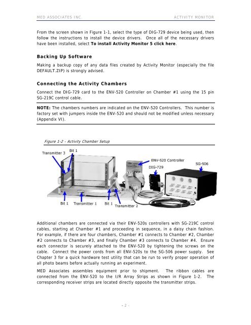
Figure 1-2 - Activity Chamber Setup<br />
Additional chambers are connected via their ENV-520s controllers with SG-219C control<br />
cables, starting at Chamber #1 and proceeding in sequence, in a daisy chain fashion.<br />
For example, if there are four chambers, Chamber #1 connects to Chamber #2, Chamber<br />
#2 connects to Chamber #3, and finally Chamber #3 connects to Chamber #4. Ensure<br />
each connector is securely attached to the ENV-520 by tightening the screws on the<br />
cable. Connect the power cords from all ENV-520s to the SG-506 power supply. See<br />
Chapter 3 for a quick hardware test utility that can be run to verify proper operation of<br />
all photo beams before actually running an experiment.<br />
MED Associates assembles equipment prior to shipment. The ribbon cables are<br />
connected from the ENV-520 to the I/R Array Strips as shown in Figure 1-2. The<br />
corresponding receiver strips are located directly opposite the transmitter strips.<br />
- 2 -