Druck-Materie 20b.qxd - JUWEL - Forschungszentrum Jülich
Druck-Materie 20b.qxd - JUWEL - Forschungszentrum Jülich
Druck-Materie 20b.qxd - JUWEL - Forschungszentrum Jülich

You also want an ePaper? Increase the reach of your titles
YUMPU automatically turns print PDFs into web optimized ePapers that Google loves.
5. THE OPTIMISATION OF MULTIPLY GROOVED MODERATORS<br />
One of the common ways to improve the flux from solid methane is to add a series of<br />
narrow grooves into the moderator. This presents us with a huge parameter space to study, so<br />
we have selected a few key points in this space to give us an idea about the possible performance.<br />
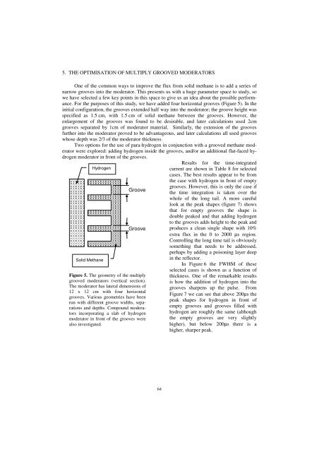
For the purposes of this study, we have added four horizontal grooves (Figure 5). In the<br />
initial configuration, the grooves extended half way into the moderator; the groove height was<br />
specified as 1.5 cm, with 1.5 cm of solid methane between the grooves. However, the<br />
enlargement of the grooves was found to be desirable, and later calculations used 2cm<br />
grooves separated by 1cm of moderator material. Similarly, the extension of the grooves<br />
further into the moderator proved to be advantageous, and later calculations all used grooves<br />
whose depth was 2/3 of the moderator thickness.<br />
Two options for the use of para-hydrogen in conjunction with a grooved methane moderator<br />
were explored: adding hydrogen inside the grooves, and/or an additional flat-faced hydrogen<br />
moderator in front of the grooves.<br />
Hydrogen<br />
Solid Methane<br />
Groove<br />
Groove<br />
Figure 5. The geometry of the multiply<br />
grooved moderators (vertical section).<br />
The moderator has lateral dimensions of<br />
12 x 12 cm with four horizontal<br />
grooves. Various geometries have been<br />
run with different groove widths, separations<br />
and depths. Compound moderators<br />
incorporating a slab of hydrogen<br />
moderator in front of the grooves were<br />
also investigated.<br />
64<br />
Results for the time-integrated<br />
current are shown in Table 8 for selected<br />
cases. The best results appear to be from<br />
the case with hydrogen in front of empty<br />
grooves. However, this is only the case if<br />
the time integration is taken over the<br />
whole of the long tail. A more careful<br />
look at the peak shapes (figure 7) shows<br />
that for empty grooves the shape is<br />
double peaked and that adding hydrogen<br />
to the grooves adds height to the peak and<br />
produces a clean single shape with 10%<br />
extra flux in the 0 to 2000 µs region.<br />
Controlling the long time tail is obviously<br />
something that needs to be addressed,<br />
perhaps by adding a poisoning layer deep<br />
in the reflector.<br />
In Figure 6 the FWHM of these<br />
selected cases is shown as a function of<br />
thickness. One of the remarkable results<br />
is how the addition of hydrogen into the<br />
grooves sharpens up the pulse. From<br />
Figure 7 we can see that above 200µs the<br />
peak shapes for hydrogen in front of<br />
empty grooves and grooves filled with<br />
hydrogen are roughly the same (although<br />
the empty grooves are very slightly<br />
higher), but below 200µs there is a<br />
higher, sharper peak.