Druck-Materie 20b.qxd - JUWEL - Forschungszentrum Jülich
Druck-Materie 20b.qxd - JUWEL - Forschungszentrum Jülich
Druck-Materie 20b.qxd - JUWEL - Forschungszentrum Jülich

Create successful ePaper yourself
Turn your PDF publications into a flip-book with our unique Google optimized e-Paper software.
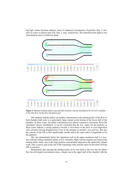
ing high volume fractions indicate zones of enhanced concentration of particles (Fig. 2, bottom)<br />
or zones of almost pure LH2 (Fig. 2, top), respectively. The transition from high to low<br />
concentration areas is relatively sharp.<br />
Figure 3. Methane hydrate pellets (top) and LH2 (bottom) velocity distribution for 20 vol% of pellets<br />
in the inlet flow for the first calculation grid<br />
The methane hydrate pellets are mainly concentrated at the turning points of the flow in<br />
both chamber halfs and, to a particularly large extend, at the bottom of the lower half of the<br />
chamber. In these zones, the pellet concentration has almost reached its maximum. From the<br />
calculated velocity distribution, it can be concluded that the low values for the particles in<br />
those zones indicate a strong tendency towards a slow-down of the flow or even deposition<br />
with velocities having dropped from 4 m/s at the entrance to around 1 m/s and less. But also<br />
the velocity of the LH2 is here significantly smaller and in the same order of magnitude as for<br />
the particles.<br />
The area immediately below the separation wall in the upper moderator half is a location<br />
with prevailing continuous phase at low velocities. High-velocity regions are found at the<br />
turning points where, due to the large particle concentration adjacent to the spherically shaped<br />
walls, only a narrow gap at the end of the separating walls remains open for the faster flowing<br />
LH2 or particles.<br />
Immediately after passing the turning points on its way back to the exit, the two-phase<br />
flow has developed recirculation zones, a larger one in the upper half of the chamber with the<br />
82