Druck-Materie 20b.qxd - JUWEL - Forschungszentrum Jülich
Druck-Materie 20b.qxd - JUWEL - Forschungszentrum Jülich
Druck-Materie 20b.qxd - JUWEL - Forschungszentrum Jülich

You also want an ePaper? Increase the reach of your titles
YUMPU automatically turns print PDFs into web optimized ePapers that Google loves.
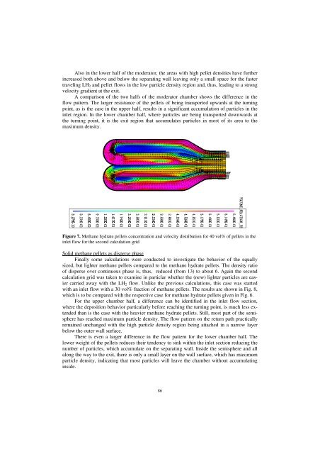
Also in the lower half of the moderator, the areas with high pellet densities have further<br />
increased both above and below the separating wall leaving only a small space for the faster<br />
traveling LH2 and pellet flows in the low particle density region and, thus, leading to a strong<br />
velocity gradient at the exit.<br />
A comparison of the two halfs of the moderator chamber shows the difference in the<br />
flow pattern. The larger resistance of the pellets of being transported upwards at the turning<br />
point, as is the case in the upper half, results in a significant accumulation of particles in the<br />
inlet region. In the lower chamber half, where particles are being transported downwards at<br />
the turning point, it is the exit region that accumulates particles in most of its area to the<br />
maximum density.<br />
Figure 7. Methane hydrate pellets concentration and velocity distribution for 40 vol% of pellets in the<br />
inlet flow for the second calculation grid<br />
Solid methane pellets as disperse phase<br />
Finally some calculations were conducted to investigate the behavior of the equally<br />
sized, but lighter methane pellets compared to the methane hydrate pellets. The density ratio<br />
of disperse over continuous phase is, thus, reduced (from 13) to about 6. Again the second<br />
calculation grid was taken to examine in particlar whether the (now) lighter particles are easier<br />
carried away with the LH2 flow. Unlike the previous calculations, this case was started<br />
with an inlet flow with a 30 vol% fraction of methane pellets. The results are shown in Fig. 8,<br />
which is to be compared with the respective case for methane hydrate pellets given in Fig. 6.<br />
For the upper chamber half, a difference can be identified in the inlet flow section,<br />
where the deposition behavior particularly before reaching the turning point, is much less extended<br />
than is the case with the heavier methane hydrate pellets. Still, most part of the semisphere<br />
has reached maximum particle density. The flow pattern on the return path practically<br />
remained unchanged with the high particle density region being attached in a narrow layer<br />
below the outer wall surface.<br />
There is even a larger difference in the flow pattern for the lower chamber half. The<br />
lower weight of the pellets reduces their tendency to sink within the inlet section reducing the<br />
number of particles, which accumulate on the separating wall. Inside the semisphere and all<br />
along the way to the exit, there is only a small layer on the wall surface, which has maximum<br />
particle density, indicating that most particles will leave the chamber without accumulating<br />
inside.<br />
86