

Medical Applications User Guide (pdf) - Freescale Semiconductor
Medical Applications User Guide (pdf) - Freescale Semiconductor
Medical Applications User Guide (pdf) - Freescale Semiconductor

Create successful ePaper yourself
Turn your PDF publications into a flip-book with our unique Google optimized e-Paper software.
7.2<br />
Signal Acquisition<br />
This application is non-invasive because the<br />
optical sensor is composed of two LEDs<br />
that transmit light through the skin (finger<br />
or earlobe) to a photodiode. One LED is red<br />
with a wavelength of 660 nm and the other is<br />
infrared with a wavelength of 910 nm. The skin<br />
absorbs the light received by the photodiode.<br />
Each wavelength provides different data to<br />
calculate the percentage of hemoglobin.<br />
Deoxygenated and oxygenated hemoglobin<br />
absorb different wavelengths. Deoxygenated<br />
hemoglobin has absorption of around 660<br />
nm and oxygenated hemoglobin has higher<br />
absorption at 910 nm. These signals depend<br />
on the actual blood pressure, therefore the<br />
heart rate can also be measured.<br />
SaO2 as R<br />
R = log 10 (I ac ) λ1<br />
log10(I ac ) λ2<br />
Iac= Light intensity at λ1 or λ2, where only AC level<br />
is present λ1 or λ2 are the wavelengths used.<br />
7.3<br />
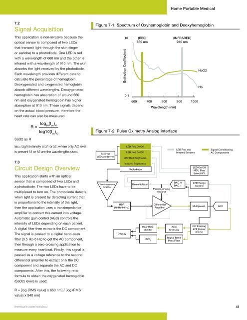
Circuit Design Overview<br />
This application starts with an optical<br />
sensor that is composed of two LEDs and<br />
a photodiode. The two LEDs have to be<br />
multiplexed to turn on. The photodiode detects<br />
when light is present by detecting current that<br />
is proportional to the intensity of the light,<br />
then the application uses a transimpedance<br />
amplifier to convert this current into voltage.<br />
Automatic gain control (AGC) controls the<br />
intensity of LEDs depending on each patient.<br />
A digital filter then extracts the DC component.<br />
The signal is passed to a digital band-pass<br />
filter (0.5 Hz–5 Hz) to get the AC component,<br />
then through a zero-crossing application to<br />
measure every heartbeat. Finally, this signal is<br />
passed as a voltage reference to the second<br />
differential amplifier to extract only the DC<br />
component and separate the AC and DC<br />
components. After this, the following ratio<br />
formula to obtain the oxygenated hemoglobin<br />
(SaO2) levels is used:<br />
R = [log (RMS value) x 660 nm] / [log (RMS<br />
value) x 940 nm]<br />
Home Portable <strong>Medical</strong><br />
Figure 7-1: Spectrum of Oxyhemoglobin and Deoxyhemoglobin<br />
Figure 7-1: Spectrum of Oxyhemoglobin and Deoxyhemoglobin<br />
Extinction Coeffiecient 10(RED)<br />
0.1<br />
freescale .com/medical 41<br />
600<br />
660 nm<br />
(INFRARED)<br />
940 nm<br />
700 800 900 1000<br />
Wavelength (nm)<br />
Figure 7-2: Pulse Oximetry Analog Interface<br />
Figure 7-2: Pulse Oximetry Analog Interface<br />
External<br />
LED and Driver<br />
Transimpedance<br />
Amplifier<br />
RBF<br />
(40 Hz-60 Hz)<br />
Display<br />
LED Red On/Off<br />
LED Red On/Off<br />
LED Red Brightness<br />
Infrared Brightness<br />
Photodiode<br />
Demultiplexer<br />
Hear Rate<br />
Monitor<br />
SaO 2<br />
Pseudo Analog<br />
Ground<br />
Differential<br />
Amplifier<br />
Zero<br />
Crossing<br />
LED Red and<br />
Infrared Sensors<br />
DAC_0<br />
DAC_1<br />
Digital Band<br />
Pass Filter<br />
HbO2<br />
Hb<br />
LED On/Off<br />
MCU Pins<br />
Select 0/1<br />
LED Range<br />
Control<br />
Multiplexer<br />
DC Tracking<br />
LPF (below<br />
0.5 Hz)<br />
Signal Conditioning<br />
AC Components<br />
ADC


