

Medical Applications User Guide (pdf) - Freescale Semiconductor
Medical Applications User Guide (pdf) - Freescale Semiconductor
Medical Applications User Guide (pdf) - Freescale Semiconductor

Create successful ePaper yourself
Turn your PDF publications into a flip-book with our unique Google optimized e-Paper software.
Diagnostic and Therapy Devices<br />
The preparation of an air and oxygen blender<br />
generally consists of attaching a 50 PSI air<br />
and oxygen source to the device. After the<br />
source gases are attached, inlet pressures<br />
may be checked on some blenders by<br />
checking the pressure-attached pressure<br />
gauge. After the inlet gases are attached and<br />
the air and oxygen blender is well secured<br />
to a stand or wall mount, it is ready for use.<br />
The MCU uses a PWM to control the blender<br />
electro valves through a motor control design.<br />
Early ventilator designs relied on mechanical<br />
blenders to provide premixed gas to a single<br />
flow control valve. With the availability of<br />
high-quality flow sensors and processing<br />
capabilities, accurate mixing becomes<br />
possible by using separate flow valves for<br />
air and oxygen. Because air already contains<br />
about 21 percent oxygen, the total flow<br />
control command between the oxygen and air<br />
valve is divided ratiometrically. For extreme<br />
mix settings, the valve that supplies the minor<br />
flow at low total flow requirements may fall<br />
below the resolution limits that either flow<br />
delivery or measurement can provide. An<br />
accurate delivered mix depends on accurate<br />
flow delivery, but if accurate and reliable<br />
oxygen sensors are used, improved mix<br />
accuracy may be possible by feeding back a<br />
measured concentration for mix correction.<br />
Then, if the patient needs more pressure, the<br />
MCU activates the compressor.<br />
For more information on how to build a<br />
ventilator/respirator, download Ventilator/<br />
Respirator Hardware and Software Design<br />
Specification (document DRM127) from<br />
freescale.com.<br />
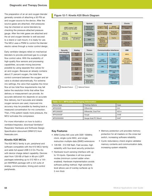
Kinetis K20 MCUs<br />
The K20 MCU family is pin, peripheral and<br />
software compatible with the K10 MCU family<br />
and adds full-speed USB 2.0 On-The-Go<br />
with device charge detect capability. Devices<br />
start from 128 KB of flash in 80-pin LQFP<br />
packages extending up to 512 KB in a 144pin<br />
MAPBGA package with a rich suite of<br />
analog, communication, timing and control<br />
peripherals.<br />
Figure Figure 11-9: 12-7: Kinetis Kinetis K20 K20 Block Block Diagram Diagram<br />
Security<br />
and Integrity<br />
Cyclic<br />
Redundancy<br />
Check (CRC)<br />
Core<br />
ARM ® Cortex-M4<br />
50/72/100/120 MHz<br />
Debug<br />
Interfaces<br />
Interrupt<br />
Controller<br />
Standard Feature<br />
Key Features<br />
• ARM Cortex-M4 core with DSP, 100MHz<br />
clock, single cycle MAC, and single<br />
instruction multiple data (SIMD) extensions<br />
• 128 KB - 512 KB flash. Fast access, high<br />
reliability with four-level security protection<br />
• Hardware touch-sensing interface with up<br />
to 16 inputs. Operates in all low-power<br />
modes (minimum current adder when<br />
enabled). Hardware implementation avoids<br />
software polling method. High sensitivity<br />
level allows use of overlay surfaces up to<br />
5 mm thick<br />
System Memories<br />
Internal and<br />
External<br />
Watchdogs<br />
Memory<br />
Protection Unit<br />
(MPU)<br />
Xtrinsic<br />
Low-Power<br />
Touch-Sensing<br />
Interface<br />
• Memory protection unit provides memory<br />
protection for all masters on the cross bar<br />
switch, increasing software reliability<br />
• Cyclic redundancy check engine validates<br />
memory contents and communication data,<br />
increasing system reliability<br />
68 <strong>Medical</strong> <strong>Applications</strong> <strong>User</strong> <strong>Guide</strong><br />
DSP<br />
Floating Point<br />
Unit (FPU)<br />
Analog<br />
16-bit<br />
ADC<br />
PGA<br />
Analog<br />
Comparator<br />
6-bit<br />
DAC<br />
12-bit<br />
DAC<br />
Voltage<br />
Reference<br />
DMA<br />
Low-Leakage<br />
Wake-Up Unit<br />
Timers<br />
FlexTimer<br />
Carrier<br />
Modulator<br />
Transmitter<br />
Programmable<br />
Delay Block<br />
Periodic<br />
Interrupt<br />
Timers<br />
Low-Power<br />
Timer<br />
Independent<br />
Real-Time<br />
Clock (RTC)<br />
Optional Feature<br />
Program Flash<br />
(32 KB to 1 MB)<br />
FlexMemory<br />
(32 KB to 512 KB)<br />
(2 to 16 KB EE)<br />
Serial<br />
Programming<br />
Interface<br />
(EzPort)<br />
NAND Flash<br />
Controller<br />
SRAM<br />
(8 KB to 128 KB)<br />
External<br />
Bus Interface<br />
(FlexBus)<br />
Cache<br />
Clocks<br />
Phase-Locked<br />
Loop<br />
Frequency-<br />
Locked Loop<br />
Low/High-<br />
Frequency<br />
Oscillators<br />
Internal<br />
Reference<br />
Clocks<br />
Communication Interfaces HMI<br />
I 2 C<br />
UART<br />
(ISO 7816)<br />
SPI<br />
CAN<br />
I 2 S<br />
Secure<br />
Digital Host<br />
Controller<br />
(SDHC)<br />
USB On-the-Go<br />
(LS/FS)<br />
USB On-the-Go<br />
(HS)<br />
USB Device<br />
Charger Detect<br />
(DCD)<br />
USB Voltage<br />
Regulator<br />
Table 12-1: MPXx2050 Packaging Information<br />
Device Type Packing Options Case<br />
MPX2050D Differential 344<br />
MPC2050DP Differential, Dual Port 423 A<br />
MPX2050GP Gauge 344B<br />
MPX2050GSX Gauge Axial PC Mount 344F<br />
GPIO


