

Medical Applications User Guide (pdf) - Freescale Semiconductor
Medical Applications User Guide (pdf) - Freescale Semiconductor
Medical Applications User Guide (pdf) - Freescale Semiconductor

Create successful ePaper yourself
Turn your PDF publications into a flip-book with our unique Google optimized e-Paper software.
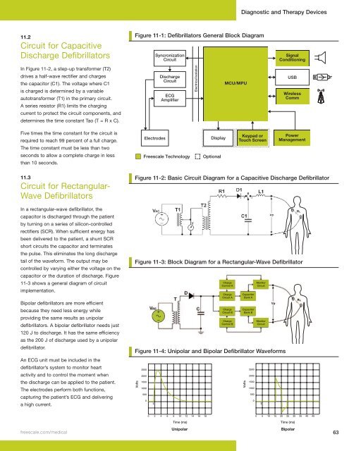
11.2<br />
Circuit for Capacitive<br />
Discharge Defibrillators<br />
In Figure 11-2, a step-up transformer (T2)<br />
drives a half-wave rectifier and charges<br />
the capacitor (C1). The voltage where C1<br />
is charged is determined by a variable<br />
autotransformer (T1) in the primary circuit.<br />
A series resistor (R1) limits the charging<br />
current to protect the circuit components, and<br />
determines the time constant Tao (T = R x C).<br />
Five times the time constant for the circuit is<br />
required to reach 99 percent of a full charge.<br />
The time constant must be less than two<br />
seconds to allow a complete charge in less<br />
than 10 seconds.<br />
11.3<br />
Circuit for Rectangular-<br />
Wave Defibrillators<br />
In a rectangular-wave defibrillator, the<br />
capacitor is discharged through the patient<br />
by turning on a series of silicon-controlled<br />
rectifiers (SCR). When sufficient energy has<br />
been delivered to the patient, a shunt SCR<br />
short circuits the capacitor and terminates<br />
the pulse. This eliminates the long discharge<br />
tail of the waveform. The output may be<br />
controlled by varying either the voltage on the<br />
capacitor or the duration of discharge. Figure<br />
11-3 shows a general diagram of circuit<br />
implementation.<br />
Bipolar defibrillators are more efficient<br />
because they need less energy while<br />
providing the same results as unipolar<br />
defibrillators. A bipolar defibrillator needs just<br />
120 J to discharge. It has the same efficiency<br />
as the 200 J of discharge used by a unipolar<br />
defibrillator.<br />
An ECG unit must be included in the<br />
defibrillator’s system to monitor heart<br />
activity and to control the moment when<br />
the discharge can be applied to the patient.<br />
The electrodes perform both functions,<br />
capturing the patient’s ECG and delivering<br />
a high current.<br />
Defibrillator<br />
Defibrillator<br />
Figure 11-1: Defibrillators General Block Diagram<br />
Syncronization<br />
Circuit<br />
Syncronization<br />
Circuit<br />
Electrodes<br />
Electrodes<br />
Discharge<br />
Circuit<br />
Discharge<br />
Circuit<br />
ECG<br />
Amplifier<br />
ECG<br />
Amplifier<br />
<strong>Freescale</strong> Technology<br />
<strong>Freescale</strong> Technology<br />
Optional<br />
MCU/MPU<br />
Diagnostic and Therapy Devices<br />
Signal<br />
Conditioning<br />
Signal<br />
Conditioning<br />
Unipolar Bipolar<br />
freescale .com/medical 63<br />
Electrical Isolation<br />
Electrical Isolation<br />
Display<br />
Optional<br />
Display<br />
MCU/MPU<br />
Keypad or<br />
Touch Screen<br />
Keypad or<br />
Touch Screen<br />
USB<br />
USB<br />
Wireless<br />
Comm<br />
Wireless<br />
Comm<br />
Power<br />
Management<br />
Power<br />
Management<br />
Figure 10-2: Basic Circuit Diagram for a Capacitive Discharge Defibrillator<br />
Figure 11-2: Basic Circuit Diagram for a Capacitive Discharge Defibrillator<br />
Figure 10-3: 11-3: Block Block Diagram Diagram for for a Rectangular-Wave a Rectangular-Wave Defibrillator Defibrillator<br />
Figure 10-4: Unipolar Defibrillator Waveform<br />
Volts<br />
2500<br />
2000<br />
1500<br />
1000<br />
500<br />
0<br />
0<br />
1<br />
2 4 6 8 10<br />
Time (ms)<br />
12 14 16 18<br />
Charge<br />
Control A<br />
Charge<br />
Circuit A<br />
Charge<br />
Circuit B<br />
Charge<br />
Control B<br />
Capacitor<br />
Bank A<br />
Capacitor<br />
Bank B<br />
Monitor<br />
Circuit<br />
Monitor<br />
Circuit<br />
Figure 11-4: Unipolar and Bipolar Defibrillator Waveforms<br />
Figure 10-5: Bipolar Defibrillator Waveform<br />
Volts<br />
2500<br />
2000<br />
1500<br />
1000<br />
500<br />
0<br />
0<br />
1<br />
5 10 15 20 25<br />
Time (ms)<br />
30 35 40 45


