

Medical Applications User Guide (pdf) - Freescale Semiconductor
Medical Applications User Guide (pdf) - Freescale Semiconductor
Medical Applications User Guide (pdf) - Freescale Semiconductor

You also want an ePaper? Increase the reach of your titles
YUMPU automatically turns print PDFs into web optimized ePapers that Google loves.
10.4<br />
Filtering ECG<br />
The ECG has three common noise sources:<br />
• Baseline wander<br />
• Power line interference<br />
• Muscle noise<br />
The baseline wander is caused by electrode<br />
impedance, respiration, body movements and<br />
low- and high-frequency noise. This makes<br />
it necessary to use a band-pass filter as<br />
described in Chapter 5, Heart Rate Monitor. To<br />
eliminate the low-frequency noise, a high-pass<br />
filter with a cut-off frequency of 0.67 Hz is used,<br />
because this corresponds to the slowest heart<br />
rate of around 40 beats per minute. However,<br />
because this is not an absolute data point, it<br />
is better to use a cut-off frequency of 0.5 Hz.<br />
Figure 10-5 shows a basic implementation<br />
circuit that detects the electrical currents<br />
through the electrodes.<br />
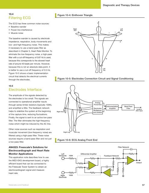
10.5<br />
Electrodes Interface<br />
The amplitude of the signals detected by<br />
the electrodes is too small. The signals are<br />
connected to operational amplifier inputs<br />
through series limiter resistors (typically 100K),<br />
and amplified a little. The feedback network<br />
helps to stabilize the system at the beginning<br />
of the capture time, reducing fluctuations.<br />
Finally, the signal is sent to an active low-pass<br />
filter. The filter eliminates the high-frequency<br />
noise which might be induced by the AC line.<br />
Other noise sources such as respiration and<br />
muscular movement (low-frequency noise) are<br />
filtered using a high-pass filter. These noise<br />
sources require a band-pass filter and not just<br />
a low-pass filter.<br />
AN4323: <strong>Freescale</strong>’s Solutions for<br />
Electrocardiograph and Heart Rate<br />
Monitor <strong>Applications</strong><br />
This application note describes how to use<br />
the MED-EKG development board, a highly<br />
efficient board that can be connected to<br />
the <strong>Freescale</strong> Tower System to obtain an<br />
electrocardiogram signal and measure<br />
heart rate.<br />
Figure 10-4: Einthoven Triangle<br />
Figure 9-4: Einthoven Triangle<br />
Right<br />
Arm<br />
Diagnostic and Therapy Devices<br />
freescale .com/medical 57<br />
–<br />
-<br />
Y<br />
II III<br />
Figure 10-5: Electrodes Connection Circuit and Signal Conditioning<br />
Figure 9-5: Electrodes Connection Circuit and Signal Conditioning<br />
Right Hand<br />
Right Leg Left Leg<br />
Left Hand<br />
+<br />
Analog<br />
Frond End<br />
Electrodes<br />
Multiplexer<br />
and Isolator<br />
Figure 10-6: ECG Analog Front End<br />
Figure 9-6: ECG Analog Front End<br />
Left<br />
Electrode<br />
Right<br />
Electrode<br />
100K<br />
100K<br />
Differential Amplifier<br />
+<br />
Left<br />
Leg<br />
I<br />
+<br />
Instrumentation<br />
Amplifier<br />
Feedback Network<br />
–<br />
Left<br />
Arm<br />
X<br />
Band Pass<br />
Filter<br />
Filter Network<br />
To MCU<br />
ADC input<br />
Output


