- Page 1 and 2: This document was too large to scan
- Page 3 and 4: DMJM H&N AECQM RPP-24544 REV Id Pag
- Page 5 and 6: 0 DMJM H&N I AECOM Calculation No 1
- Page 7 and 8: DMJM H&N AECOM I Calculation No 145
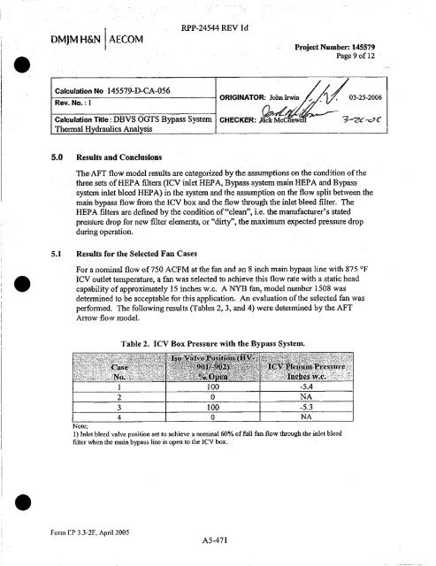
- Page 9: • DMJM H&N I AECOM Calculation No
- Page 13 and 14: I• • r1 LJ DM]M H&N AECOM I Cal
- Page 15 and 16: • • i DMJM H&N ( AECOM Calculat
- Page 17 and 18: • RPP-24544 REV id Calculation No
- Page 19 and 20: • LJ C', B A Ii wm" BOY NOTES, ©
- Page 21 and 22: • 0 0 . 78. 5. 4 3 RPP-24544 REV
- Page 23 and 24: • u ^I / s FI _- / I =I I 1 / 1 1
- Page 25 and 26: i RPP-24544 REV 1d Calculation No.
- Page 27 and 28: • • F E BI 6 A 8 7 6 a 8 SECTIO
- Page 29 and 30: 0 Q C e A 1 i e 13 7 6 5 4 3 2 1 wo
- Page 31 and 32: V m ` 1 1 y j9ppL{ bi N gp N ^ R\
- Page 33 and 34: • • • RPP-24544 REV Id Calcul
- Page 35 and 36: E 0 RPP-24544 REV 1d Calculation No
- Page 37 and 38: u E RPP-24544 RFV" a Calculation No
- Page 39 and 40: L 1 RPP-24544 REV Id Calculation No
- Page 41 and 42: • • • RPP-24544 REV ld Calcul
- Page 43 and 44: • E • RPP-24544 REV ld Calculat
- Page 45 and 46: • • RPP-24544 REV Id Calculatio
- Page 47 and 48: • • • RPP-24544 REV Id Calcul
- Page 49 and 50: • RPP-24544 REV Id Calculation No
- Page 51 and 52: 7 • • RPP-24544 REV let Calcula
- Page 53 and 54: • AFTAO 0 RPP-24544 REV Id Calcul
- Page 55 and 56: • • . RPP-24544 REV 18 alculati
- Page 57 and 58: 0 RPP-24544 REV Id Calculation No.
- Page 59 and 60: • RPP-24544 REV Id Calculation No
- Page 61 and 62:
• • RPP-24544 REV Id Calculatio
- Page 63 and 64:
• • RPP-24544 RFV Id Calculatio
- Page 65 and 66:
III • • E RPP-24544 REV id Calc
- Page 67 and 68:
0 • • RPP-24544 REV Id Calculat
- Page 69 and 70:
• I* RPP-24544 REV Id Calculation
- Page 71 and 72:
I • • • RPP-24544 REV Id Calc
- Page 73 and 74:
• • AFTAnmvw ooulglt (ids) 2!25
- Page 75 and 76:
• • AFT Anow 3.0 OUtpW - (3 01
- Page 77 and 78:
0 • • AFfA 3.00utput (So/5) 312
- Page 79 and 80:
• is This page intentionally left
- Page 81 and 82:
a A . • Calculation No. 145579-D-
- Page 83 and 84:
0 Y, inaw . • Calculation No. 145
- Page 85 and 86:
a Y, in A Calculation No. 145579-DA
- Page 87 and 88:
• • Calculation No. 145579-D-06
- Page 89 and 90:
v, A • • Calculation No. 145579
- Page 91 and 92:
• . Calculation No. 145579-D-606,
- Page 93 and 94:
a in w Calculation No. 145579-DA6,
- Page 95 and 96:
0 • RPP-24544 REV ld Calculation
- Page 97 and 98:
ON • • Calculation No. 145579-D
- Page 99 and 100:
h OGTS Bypass External Convection a
- Page 101 and 102:
• • RPP-24544'REV id This page
- Page 103 and 104:
f- - ANSI 816.1041976 Maximum Leaka
- Page 105 and 106:
Y, in rn Pressure Blower 1503 Steel
- Page 107 and 108:
RPP-24544 REV ld Calculation No. 14
- Page 109 and 110:
• • RPP`-24544 REV Id Calculati
- Page 111 and 112:
• • RPP-24544'REV id Calculatio
- Page 113 and 114:
1 1 ___ t-^q f ^ 1 v^ci-.- 1u o -^-
- Page 115 and 116:
. • RPP-24544 REV ld AJAR A4/A, 0
- Page 117 and 118:
I Eq. 9 •, 1 11 lwl 1111 'LL, , ,
- Page 119 and 120:
• • EA5-2^V}r, 45 Degree, Cotwe
- Page 121 and 122:
. • RPP-24544 REV Id CalculationN
- Page 123 and 124:
Dud Desiga EUS-31Yc,:Dr rlOin.. Com
- Page 125 and 126:
• • E DuctDesign EM-3 Tee,Dr >
- Page 127 and 128:
a Y, 00 -11 ^rnll P P 8 pp POP= L L
- Page 129 and 130:
. • 35.43 SD4.7. Tmsl tlon, Round
- Page 131 and 132:
Daet Design RPP-24544'REV 1'd CR3.9
- Page 133 and 134:
• I RPP-24544 REV Id Calculation
- Page 135 and 136:
• • • ERM Maw. 90 Degree, Var
- Page 137 and 138:
0 • Duct Design SR3-1 Elbow, 991)
- Page 139 and 140:
• • • RPP-24544 REV Id Calcul
- Page 141 and 142:
2. Spreadsheet Owner, Organization,
- Page 143 and 144:
DMJM H&N A3Ivi Calculation No 14557
- Page 145 and 146:
W RPP-24544 REV I Calculation No. 1
- Page 147 and 148:
.*I— RPP-24544 REV I d Calculatio
- Page 149 and 150:
3 lh all 0 ^t OGTS Bypass System Fl
- Page 151 and 152:
a OGTS Bypass System Fluid Flow Mod
- Page 153 and 154:
io. tj chi, I OGTS Bypass System Fl
- Page 155 and 156:
v, OGTS Bypass System Fluid Flow Mo
- Page 157 and 158:
v^ OGTS Bypass System Fluid Flow Mo
- Page 159 and 160:
a Y, OGTS Bypass System Fluid Flow
- Page 161 and 162:
• I Q • D A a RPP-24544 REV I C
- Page 163 and 164:
• 11 r1 LJ Tel: RPP-24544 REV id
- Page 165 and 166:
37th.. of C^ t 01G I'S Bypass Syste
- Page 167 and 168:
1) "I HEPA Fnhcr, 36-NO2-131 Flande
- Page 169 and 170:
i Y" c^ N j of OGTS Bypass External
- Page 171 and 172:
Y, w i Radiation component: I OGTS
- Page 173 and 174:
££9-Sd PI AgS tt5K-d" _ N, i— ^
- Page 175 and 176:
• • L J RPP-24544 REV Id This p
- Page 177 and 178:
• • CALCULATION SHEET M RPP-245
- Page 179 and 180:
CALCULATION SHEET CAM Nos 145579-V-
- Page 181 and 182:
• Calculation No. 145579-V-CA-004
- Page 184 and 185:
• is Calculation No. 145579-V-CA-
- Page 186 and 187:
0 \J • RPP-24544 REV Id - ^(q Pro
- Page 189:
7 0 RPP-24544 REV I 145579-V-CA-004
- Page 192 and 193:
• 11 0 ^ 3j o N^ '/ M.^^^9 RPP-24
- Page 194 and 195:
• i r RPP-24544 REV 1 d 145579-V-
- Page 196 and 197:
0 RPP-24544 REV I 145579-V-CA-004 A
- Page 198 and 199:
RPP-24544 REV 1 d 0 Nonresidgnt(al
- Page 200 and 201:
C g 41 N O 2 RPP-24544 REV Id 33.4
- Page 202 and 203:
11 0 RPP-24544 REV I 145579 -V-CA-0
- Page 204 and 205:
W • • 3. From the Ratings on pa
- Page 206 and 207:
E • Wafer Pressure Drop n 100.0 0
- Page 208:
0 RPP-24544 REV I 145579-V-CA-004 A
- Page 211 and 212:
0 0 Ln CAST BONNET Provides flu id
- Page 213 and 214:
STEP 4: Calculate the area required
- Page 215 and 216:
0 u • . . - I .E COMMON DIMENSION
- Page 217 and 218:
RPP-24544 REV )d CS & STC Series in
- Page 219 and 220:
• is RPP-24544 REV I d • Figure