0 - Hanford Site
0 - Hanford Site
0 - Hanford Site
Create successful ePaper yourself
Turn your PDF publications into a flip-book with our unique Google optimized e-Paper software.
0<br />
DMJM H&N I AECOM<br />
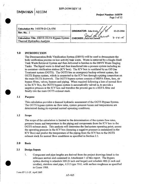
Calculation No 145579-D-CA-056<br />
Rev.<br />
RPP-24544 REV Id<br />
Project Number: 145579<br />
Page 3 of 12<br />
ORIGINATOR: John Irwin'1% 03-25-2006<br />
Calculation Title: DBVS OGTS Bypass System CHECKER: y ack McConwell<br />
Thermal Hydraulics Analysis<br />
3--eC vC<br />
1.0 INTRODUCTION<br />
The Demonstration Bulk Vitrification System (DBVS) will be used to demonstrate the<br />
bulk verification process on low activity tank waste. Waste is retrieved by a Single-Shell<br />
Tank Waste Retrieval System and then delivered in batches to the DBVS Waste Staging<br />
Tanks. The liquid waste is dried and then transferred into a process system including an<br />
in container vitrification station (ICV box). The ICV box is ventilated by an Off Gas<br />
Treatment system (OGTS). The OGTS has an emergency backup exhaust system, the<br />
OGTS Bypass system, which is connected to the ICV box through a piping connection on<br />
the main OGTS ductwork. The OGTS bypass system consists of HEPA filters, fans, air<br />
bypass filters, valves, heaters and piping. When required following a loss of normal flow<br />
to the ICV Box, the OGTS bypass system is automatically valved in, to provide a<br />
negative pressure at the ICV box and transfers the process gas to a HEPA filter and<br />
• finally into the main OGTS exhaust stack.<br />
1.1 Purpose<br />
1.2 Scope<br />
2.0 Basis<br />
This calculation provides a thennal hydraulic assessment of the OGTS Bypass System.<br />
The OGTS bypass system air flow rates, system pressure losses and temperatures are<br />
determined during its expected normal operating conditions.<br />
The scope of the calculation is limited to the determination of the system flow rates,<br />
pressure losses and temperature in the piping and components from the ICV box to the<br />
OGTS exhaust stack. This analysis will determine the fan/system operating point; assess<br />
the operating pressure in the ICV box (insuring a negative pressure is maintained in the<br />
ICV Box) and predict the temperature of the piping from the ICV box to the OGTS<br />
exhaust stack for normal flow conditions as specified in Section 2.1.<br />
2.1 Design Inputs<br />
1. Component and pipe lengths are derived from the project drawings listed in the<br />
reference section and contained in Attachment I of this report. The Bypass<br />
• system ducting is schedule I OS (8 inch and larger) and schedule 40S (6 inch and<br />
smaller), stainless steel pipe, A312 type 316L with surface roughness as specified<br />
in Crane 1988.<br />
1-'om EP 3.3-21'. April 2005<br />
A5-465


