

0 - Hanford Site
0 - Hanford Site
0 - Hanford Site

Create successful ePaper yourself
Turn your PDF publications into a flip-book with our unique Google optimized e-Paper software.
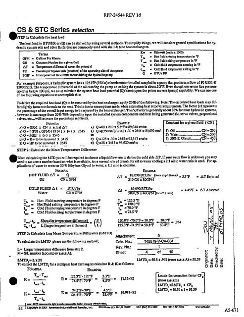
CS & STC Series selection<br />
WMP 1: Calculate the heat load<br />
RPP-24544 REV Id<br />
The heat load in BTU/HR or (Q) can be de rived by using several methods. To simplify things, we will consider general specifications for hy.<br />
draulic system oils and other fluids that are commonly used with shell & tube heat exchangers.<br />
Terms<br />
GPM . GallonsPer Minute<br />
CN . Constant Number fora given fluid<br />
AT = Temperature di0'ercndal across d= potential<br />
PSI . Pounds per Square Inch (p=um) of the operating side of the system<br />
MIT . Horsepower of the electric motor ddving the hydraulic pump Q - arm / l m<br />
r w a wowaa twos x two)<br />
Tt° a Not fluid entering tempe rature in OF<br />
T. . Hot fluid exiting temperature in OF<br />
ti. • Cold fluid iemperawn: ent ering in OF<br />
t aie a Cold fluid temperature exiting in OF<br />
For example purposes, a hydrau lic system has a 125 HP (93Kw) elec tric motor installed coupled to a pump that p roduces a flow of 80 GPM @<br />
2500 PS1G. The temperature differential of the oil entering the pump vs exiting the system Is about 53°F. Even though our return line pressure<br />
ope ra tes below 100 psi, we must calculate the system heat load potential (Q) based upon the p rime movers (pump) capability. We can use one<br />
of the fo ll<br />
owing equations to accomplish this:<br />
To de rive the required heat load (Q) to be removed by the heat exchanger, apply ONE of the following. Note: The cal culated but loads may di[<br />
fer slightly from one formula to the next. This is due to assump ti ons trade when es timating heat removal requirements. The factor (v) represents<br />
the percentage of the overall input energy to be rejected by the beat exchanger. The (v) fac tor is generally about 30% for most hydrau lic systems,<br />
. however it can range from 20'%-70% depending upon the installed system components and heat being gene ra ted (e. servo valves, proportional<br />
valves, ete—will increase the percentage required).<br />
FORMULA EX4.%ME Constant for a given fluid ( CN )<br />
A) Q - GPM x CN x actu al AT A) Q =80 x 210 x 53°F = 89,040 "R<br />
e) Q - [ (PSI x GPM) / 1714) x (v) x 2545 a) Q -[(7500x80)117141 x 30 x 2545 = 89,090 eruf 1) Oil<br />
e) Q - MIIP x (v ) x 2545 _ tin 2) Water..M.._....._._._...CN =<br />
D) Q = Kw to be removed x 3415 e) Q =125 x.30 x 2545 = 95,347 sTu4 t 3) 50%!? Glycol..._._.. = 4 0<br />
_ x) Q • HP to be removed x 2545 D) Q =28 x 3415 = 95,620 smltm<br />
•<br />
STEP 2: Calculate the Mean Tempera ture Difference<br />
When calcula ting the MTD you will be requi red to choose a li quid flow rate to derive the cold side AT. If your water flow is Unknown you may<br />
need to assume a number based on what is available. As a normal rule of thumb, for oil to water cooling a 2:1 oil to water ratio is used. For cepplica<br />
tiots of water to water or 50 % Ethylene Glycol to water, a 1:1 ratio is common.<br />
FORMMA<br />
HOT FLUID AT = Q<br />
Oil CN x GPM<br />
I xAmnE<br />
AT = 89,090^f "' uep 1em<br />
Jt a) = 5.3°F = AT Rejected<br />
COLA FLUID A t = BTU/hr<br />
89 090 BTUfhr<br />
At<br />
= 4.45°P = ^TAbsorbed<br />
Water CN xGPM<br />
x<br />
'D lora2:l ra tio)<br />
T,, . Ilot Fluid entering temperature in degrees F TI =1253 T<br />
Tee, • Hot Fluid exiting temperature in degrees F T. = 120.0 OF<br />
tin a Cold Fluid entering temperature in degrees F L, -70.09F<br />
ter„ = Cold Fluid exiting temperatu re in degrees F ter, a 74.5 OF 0 p<br />
T, a • La a S[smaller temperature difference) = rS 120.0017-70.0°17- 50.0617 a 500°F a 3M<br />
l<br />
TI, . tei1 L (larger tempe ra ture differencel \ L / 1253°F-743°F = 50.8°F 30.8°F ^{ £<br />
STEP 3: Calculate Log Mean Temperature Diffe rence Q MTD) - D<br />
Attachment<br />
9<br />
To calculate the LMTD please use the following method; Calm No.: 145579-V-CA-004<br />
L- Luger temperature difference from step 2.<br />
M a S/L number (LoeATm err TAat a A).<br />
Rev. No.:<br />
Sheet 4<br />
1<br />
of 10 0<br />
m<br />
LMTDI =L%M LMTDI=50.8x.992 (nom TAmmA)=5039 t<br />
To comet the LMT'D, for a multipass heat exchangers calculate R & K as fo ll<br />
ows: Q U<br />
FotcatuIA EXAMPLE<br />
B•n<br />
R=<br />
Th. -Tow<br />
t -^<br />
1253°F-120°F 5.3°F<br />
R=<br />
4 - F = 7V = (L17=R)<br />
the wrrec6on factor CFa<br />
r(ROM rO'<br />
=CHID, z CFa<br />
K=<br />
er<br />
Tin-t„<br />
_745°F-70°F<br />
K-<br />
124.5°F-70°F<br />
= 43°F<br />
55.4°F<br />
=<br />
(0.081=K)<br />
e=5039x1.5039<br />
,are A*9fMA0 4A"<br />
AIMbe ndaVe.naab daatp,dut. nQ aa^W r,oara<br />
^ Copyr$itOaow Arriaicart lndntriallNalTmrrateA ate. asm ttewtn wee. Z. aowo tr:t mes>, rnd000 tac tMrt nt•roto w°waare°m<br />
S


