

0 - Hanford Site
0 - Hanford Site
0 - Hanford Site

You also want an ePaper? Increase the reach of your titles
YUMPU automatically turns print PDFs into web optimized ePapers that Google loves.
0<br />
Y,<br />
inaw<br />
. • Calculation No. 145579-D-056, Rev.1<br />
Attachment 3<br />
Page 6 of 22<br />
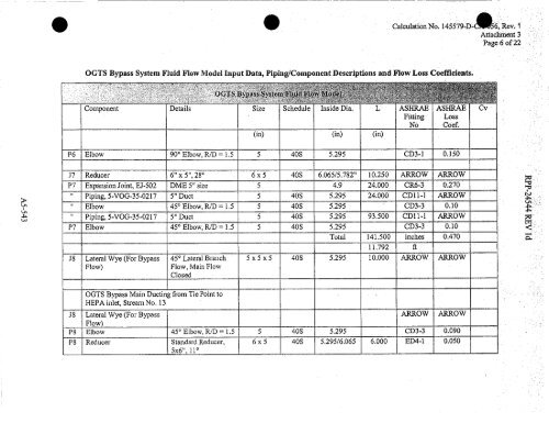
OGTS Bypass System Fluid Flow Model Input Data, Piping/Component Descriptions and Flow Loss Coefficients.<br />
?<br />
OGTS Bypa^s^^ tSyste^ tl.' pw'<br />
^ t t? x<br />
Component Details Size Schedule Inside Dia. L ASHRAE<br />
Fitting<br />
No<br />
(in) (in) (in)<br />
ASHRAE<br />
Loss<br />
Coef.<br />
P6 Elbow 90° Elbow, R/D = 1.5 5 40S 5.295 CD3-1 0.150<br />
J7 Reducer 6"x 5", 28° 6 x 5 40S 6.065/5.782" 10.250 ARROW ARROW<br />
P7 Expansion Joint, EJ-502 DME 5" size 5 4.9 24.000 CR6-3 0.270<br />
11<br />
Piping, 5-VOG-35-0217 5" Duct 5 40S 5.295 24.000 CD11-1 ARROW<br />
11<br />
Elbow 451 Elbow, R/D = 1.5 5 40S 5.295 CD3-3 0.10<br />
" Piping, 5-VOG-35-0217 5" Duct 5 40S 5.295 93.500 CD1l-1 ARROW<br />
P7 Elbow 45 1 Elbow, R/D = 1.5 5 40S 5.295 CD3-3 0.10<br />
Total 141.500 inches 0.470<br />
11.792 R<br />
J8 Lateral Wye (For Bypass 45 0 Lateral Branch 5 x 5 x 5 40S 5.295 10.000 ARROW ARROW<br />
Flow)<br />
Flow, Main Flow<br />
Closed<br />
J8<br />
OGTS Bypass Main Ducting from Tie Point to<br />
HEPA inlet, Stream No. 13<br />
Lateral Wye (For Bypass<br />
ARROW ARROW<br />
Flow<br />
P8 Elbow 45 0 Elbow, R/D = 1.5 5 40S 5.295 CD3-3 0.090<br />
P8 Reducer Standard Reducer,<br />
5x6", 11°<br />
6 x 5 40S 5.295/6.065 6.000 ED4-1 0.050<br />
Cv<br />
:a<br />
a:<br />
tnl6<<br />
a-


