

0 - Hanford Site
0 - Hanford Site
0 - Hanford Site

Create successful ePaper yourself
Turn your PDF publications into a flip-book with our unique Google optimized e-Paper software.
Y,<br />
N<br />
0 V 0 LJ<br />
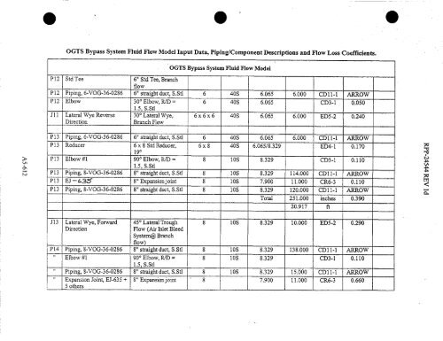
OGTS Bypass System Fluid Flow Model Input Data, Piping/Component Descriptions and Flow Loss Coefficients.<br />
P12 Std Tee 6" Std Tee, Branch<br />
OGTS Bypass System Fluid Flow Model<br />
flow<br />
P12 Piping, 6-VOG-36-0286 6" straight duct, S.Stl 6 40S 6.065 6.000 CDll-1 ARROW<br />
P12 Elbow 30° Elbow, R/D =<br />
1.5, S.Stl<br />
J11 Lateral Wye Reverse 30 0 Lateral Wye,<br />
Direction<br />
Branch Flow<br />
6 40S 6.065 CD3-1 0.050<br />
6 x 6 x 6 40S 6.065 6.000 ED5-2 0.240<br />
P13 Piping, 6-VOG-36-0286 6" straight duct, S.Stl 6 40S 6.065 6.000 CDl 1 -1 ARROW<br />
P13 Reducer 6 x 8 Std Reducer,<br />
19°<br />
P13 Elbow #1 90° Elbow, R/D =<br />
1.5, S.Stl<br />
6x8 40S 6.065/8.329 ED4-1 0.170<br />
8 los 8.329 CD3-1 0.110<br />
P13 Piping, 8-VOG-36-0286 8" straight duct, S.Stl 8 lOS 8.329 114.000 CD 11 -1 ARROW<br />
P13 EJ -&3;!^r 8" Expansion joint 8 10S 7.900 11.000 CR6-3 0.110<br />
P13 Piping, 8-VOG-36-0286 8" straight duct, S.Stl 8 lOS 8.329 120.000 CD11-1 ARROW<br />
Total 251.000 inches 0.390<br />
20.917 ft<br />
J13 Lateral Wye, Forward<br />
Direction<br />
45 0 Lateral Trough<br />
Flow (Air Inlet Bleed<br />
System@ Branch<br />
flow<br />
8 los 8.329 10.000 E135-2 0.290<br />
P14 Piping, 8-VOG-36-0286 8" straight duct, S.Stl 8 l05 8.329 138.000 CD11-1 ARROW<br />
" Elbow #1 90° Elbow, RID =<br />
1.5, S.Stl<br />
8 l05 8.329 C133-1 0.110<br />
" Piping, 8-VOG-36-0286 8" straight duct, S.Stl 8 l05 8.329 15.000 CDl l-1 ARROW<br />
" Expansion Joint, EJ-635 +<br />
5 others<br />
8" Expansionjoint 8 7.900 11.000 CR6-3 0.660<br />
^u N<br />
a<br />
MLA<br />
C^]<br />
C


