FASTENER JOINT DESIGN In applications which experience high cyclic loading analysis of the fastener loading is critical. Based on the relative stiffness of the assembly and the screw, and the external load applied, the fastener size and proper preload can be determined. Preload is normally achieved by tightening the screw. The torque required to achieve the specific preload depends on the surface lubricity at the threads and at the head, the surface finish, thread pitch, head bearing configuration, and torque wrench accuracy. PRELOAD AND EXTERNAL LOAD CONSIDERATIONS When a fastener is tightened, the load on the assembly and fastener increase. In the ideal case, the screw stretches, and the joint compresses, within the elastic limit, according to Hooke's Law. Suppose a joint has been tightened to a preload P i and additional load, P e , tending to separate the members is applied. In general in rigid assemblies, as long as the external load is less then P t it primarily decompresses the joint and has little effect on the tension in the screw. Thus even if such a load is repeatedly applied, the fastener will not fail in fatigue. However, if a repeated external load greater than P i must be applied, it should be kept to a minimum, since it produces cyclic tensioning in the screw and may lead to fatigue failure. This principle has important practical applications. Often when fasteners fail, the solution used is to switch to the next larger size. This involves changing the tooling for hole preparation and tightening, and possibly changing assembly fixtures. Most likely, merely tightening the fastener above the external load would solve the problem. For instance, a 180,000 psi tensile strength socket screw has an average endurance limit of only 15,000 psi. This means that the fastener is capable of withstanding a maximum one-time applied stress of 180,000 psi, but that a stress change felt by the fastener of more than 15,000 psi could result in a fatigue failure within a given number of cycles. A conservative formula giving the tension on a fastener which has an external load, P e is: [ ] Ks P = P + K + K P t i s c e Nomenclature Pt = Total Bolt load, lb. Pi = Preload, lb. Pe = External load, lb. Ks = Screw spring constant, lb./inch. Kc = Assembly spring constant, lb./inch. The spring constant, K, for a member is given by: 52 (area, sq. in.) (modulus of elasticity, psi) (length, in.) Since these calculations ignore factors such as bending, heat, and impact loading, they are useful as a guide only. Torque to achieve preload When screws are torqued to achieve preload, the torsional stresses on them reduces the total tensile force they can withstand before yielding. The following formula can be used to determine the effect of this torsional component: P ( S = ± t A √ 2 J A P) +( ) t x r 2 2 The desired tightening torque can be estimated using the empirical formula: T = KDP Nomenclature S t = Total tensile stress felt by bolt, psi P = Preload exerted by bolt, lb. A = Thread stress area, sq. inches T = Tightening torque, in.-lb. t = Torsion felt by screw (approximately 40% of applied torque, depending on lubricity), in.-lb. r = √A/π J = πr4 (polar moment of inertia), in. 4 2 K = Constant from 0.05 to 0.35, dimensionless D = Nominal screw diameter, inches The constant, K, is normally from 0.19 to 0.25 for a black screw. For a lubricated fastener or one with cadmium plating, K is from 0.13 to 0.17. Zinc plated screws, not lubricated, may have a K value as high as 0.30 to 0.35. For rigid parts of steel, the conservative practice is to tighten the fasteners to 75% of yield. Lower torques should be considered for flexible joints, joints with gaskets, or assemblies subject to high temperatures. Joint Design Steps 1. Calculate the assembly service load. 2. Determine relative loading on each fastener. 3. Determine the style fastener desired (hex, socket, etc.). 4. Using the highest loaded fastener in assembly, apply an appropriate safety factory based on the estimated reliability of the service load value, the quality level of the type fastener used, estimate of assembly techniques consistency, and danger of an assembly failure. Normally a safety factory could range from 1.5 to 6. 5. Determine fastener size, tightening torque, and cycle life, where applicable. 6. Specify tightening torques on drawing. Fastener Assembly Tips: 1. Preload properly. 2. Do not use split type lock washers on socket head screws or Grade 8 hex screws. 3. Use long screws when possible. 4. Avoid transverse or shear loading against the threads. 5. Keep the members clean during assembly. 6. Use wrenches that fit properly and are correctly heat treated.
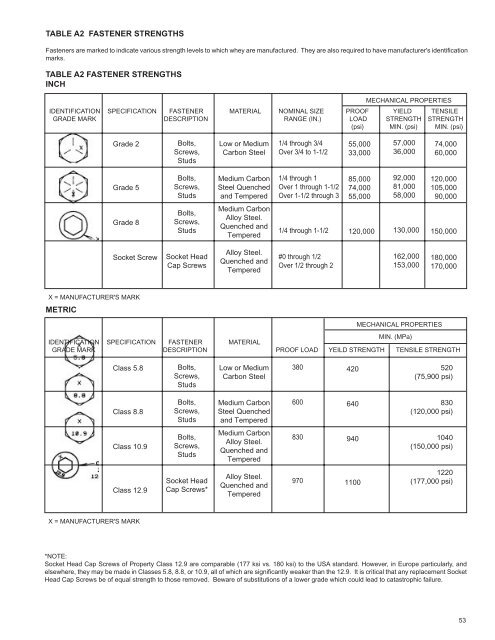
TABLE A2 FASTENER STRENGTHS Fasteners are marked to indicate various strength levels to which whey are manufactured. They are also required to have manufacturer's identification marks. TABLE A2 FASTENER STRENGTHS INCH MECHANICAL PROPERTIES IDENTIFICATION SPECIFICATION FASTENER MATERIAL NOMINAL SIZE PROOF YIELD TENSILE GRADE MARK DESCRIPTION RANGE (IN.) LOAD STRENGTH STRENGTH (psi) MIN. (psi) MIN. (psi) Grade 2 Grade 5 Grade 8 Socket Screw X = MANUFACTURER'S MARK METRIC Bolts, Screws, Studs Bolts, Screws, Studs Bolts, Screws, Studs Socket Head Cap Screws Low or Medium Carbon Steel Medium Carbon Steel Quenched and Tempered Medium Carbon Alloy Steel. Quenched and Tempered Alloy Steel. Quenched and Tempered 1/4 through 3/4 Over 3/4 to 1-1/2 1/4 through 1 Over 1 through 1-1/2 Over 1-1/2 through 3 1/4 through 1-1/2 #0 through 1/2 Over 1/2 through 2 55,000 33,000 85,000 74,000 55,000 120,000 57,000 36,000 92,000 81,000 58,000 130,000 162,000 153,000 74,000 60,000 120,000 105,000 90,000 150,000 180,000 170,000 IDENTIFICATION SPECIFICATION FASTENER MATERIAL MIN. (MPa) GRADE MARK DESCRIPTION PROOF LOAD YEILD STRENGTH TENSILE STRENGTH Class 5.8 Class 8.8 Class 10.9 Class 12.9 X = MANUFACTURER'S MARK Bolts, Screws, Studs Bolts, Screws, Studs Bolts, Screws, Studs Socket Head Cap Screws* Low or Medium Carbon Steel Medium Carbon Steel Quenched and Tempered Medium Carbon Alloy Steel. Quenched and Tempered Alloy Steel. Quenched and Tempered *NOTE: Socket Head Cap Screws of Property Class 12.9 are comparable (177 ksi vs. 180 ksi) to the USA standard. However, in Europe particularly, and elsewhere, they may be made in Classes 5.8, 8.8, or 10.9, all of which are significantly weaker than the 12.9. It is critical that any replacement Socket Head Cap Screws be of equal strength to those removed. Beware of substitutions of a lower grade which could lead to catastrophic failure. 380 600 830 970 420 640 940 1100 MECHANICAL PROPERTIES 520 (75,900 psi) 830 (120,000 psi) 1040 (150,000 psi) 1220 (177,000 psi) 53