Consolidated Tech Man - Holo-Krome
Consolidated Tech Man - Holo-Krome
Consolidated Tech Man - Holo-Krome

You also want an ePaper? Increase the reach of your titles
YUMPU automatically turns print PDFs into web optimized ePapers that Google loves.
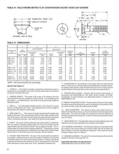
TABLE 41 HOLO-KROME METRIC FLAT COUNTERSUNK SOCKET HEAD CAP SCREWS<br />
TABLE 41 DIMENSIONS<br />
NOMINAL SIZE<br />
AND<br />
THREAD PITCH<br />
66<br />
M3 x 0.5<br />
M4 x 0.7<br />
M5 x 0.8<br />
M6 x 1<br />
M8 x 1.25<br />
M10 x 1.5<br />
M12 x 1.75<br />
M14* x 2<br />
M16 x 2<br />
M20 x 2.5<br />
D A H J T G F<br />
BODY<br />
DIAMETER<br />
MAX. MIN.<br />
3.0<br />
4.0<br />
5.0<br />
6.0<br />
8.0<br />
10.0<br />
12.0<br />
14.0<br />
16.0<br />
20.0<br />
2.86<br />
3.82<br />
4.82<br />
5.82<br />
7.78<br />
9.78<br />
11.73<br />
13.73<br />
15.73<br />
19.67<br />
THEORETICAL<br />
SHARP<br />
MAX.<br />
6.72<br />
8.96<br />
11.20<br />
13.44<br />
17.92<br />
22.40<br />
26.88<br />
30.80<br />
33.60<br />
42.00<br />
HEAD DIAMETER<br />
NOTE *Not recommended for new design.<br />
ABSOLUTE<br />
MIN.<br />
5.35<br />
7.80<br />
9.75<br />
11.70<br />
15.60<br />
19.50<br />
23.40<br />
26.52<br />
29.01<br />
36.05<br />
1.86<br />
2.48<br />
3.10<br />
3.72<br />
4.96<br />
6.20<br />
7.44<br />
8.40<br />
8.80<br />
11.00<br />
NOTES FOR TABLE 41<br />
1. LENGTH L. The length of hexagon socket flat countersunk screws is<br />
measured on a line parallel to the axis, from the plane of top of the head to<br />
the plane of the flat of the point.<br />
2. THREAD LENGTH. The length of the screw is the distance from the<br />
extreme point to the last complete or full form thread. It is controlled by the<br />
grip length, L GH as defined below. See Table 42 for grip and body lengths of<br />
standard screws.<br />
3. BODY L BH . The unthreaded cylindrical portion of the shank for screws<br />
that are not threaded to the head. This represents the minimum length of<br />
full body plus the reference head height.<br />
4. GRIP LENGTH L GH . The maximum length representing the design grip<br />
length of the screw. It is measured from the top of the head, parallel to the<br />
axis of the screw, to the face of a GO thread ring gage with the countersink<br />
and/or counterbore removed. See Table 42 for grip and body lengths.<br />
5. POINT> The points of flat countersunk cap screws shall be chamfered,<br />
with the chamfer extending slightly below the root of the thread and the<br />
edge between the flat and the chamfer may be slightly rounded. The included<br />
angle of the point shall be approximately 90°. Chamfering on screw<br />
sizes up to and including 4mm in diameter and of larger sizes with the length<br />
shorter than 0.75 times the basic screw diameter, shall be optional.<br />
6. SOCKET TRUE POSITION. The axis of the socket shall be located at<br />
true position relative to the axis of the screw within a tolerance zone having<br />
a diameter equal to 3% of the basic screw diameter or 0.26mm, whichever<br />
is greater, for nominal screw sizes up to 12mm, and equal to 6% of the basic<br />
screw diameter for sizes larger than 12mm, regardless of feature size.<br />
HEAD HEIGHT<br />
HEXAGON<br />
FILLET<br />
FLUSHNESS SOCKET<br />
KEY<br />
SOCKET<br />
EXTENSION<br />
REFER- TOLER-<br />
SIZE ENGAGEMENT<br />
WALL<br />
ABOVE D<br />
ENCE<br />
ANCE NOM.<br />
MIN. MIN. MAX.<br />
0.25<br />
0.25<br />
0.30<br />
0.35<br />
0.40<br />
0.40<br />
0.45<br />
0.50<br />
0.50<br />
0.75<br />
2.0<br />
2.5<br />
3.0<br />
4.0<br />
5.0<br />
6.0<br />
8.0<br />
10.0<br />
10.0<br />
12.0<br />
1.1<br />
1.5<br />
1.8<br />
2.4<br />
3.0<br />
3.6<br />
4.6<br />
5.5<br />
5.5<br />
7.2<br />
0.31<br />
0.45<br />
0.66<br />
0.70<br />
1.16<br />
1.62<br />
1.80<br />
1.80<br />
2.20<br />
2.20<br />
0.25<br />
0.35<br />
0.40<br />
0.50<br />
0.60<br />
0.80<br />
0.90<br />
1.00<br />
1.00<br />
1.20<br />
7. CONCENTRICITY. Concentricity of the thread with the body shall be<br />
within 0.13mm per mm of body length (unthreaded portion) full (total) indicator<br />
reading, taken directly under the head when the screw is held by the full<br />
threads closest to the head of the screw and shall not exceed 0.64mm.<br />
8. THREADS AND GAGING. Threads shall be metric coarse series, in<br />
accordance with ANSI/ASME B1.13M, Metric Screw Threads, -M Profile.<br />
Acceptability of screw threads to be determined based on System 22 of<br />
ANSI/ASME B1.3M.<br />
9. THREAD TOLERANCE CLASS> Threads shall be Tolerance Class 4g6g.<br />
For plated screws the allowance g may be consumed by the plating so that<br />
the maximum limit of size after plating shall be 4h6h.<br />
10. HEAD DIAMETERS. The maximum sharp values listed under A in<br />
Table 41 are theoretical values, as it is not practical to make the edges of the<br />
head sharp. The maximum sharp value represents the exact diameter of<br />
the hole countersunk to exactly 90° in which a screw having maximum head<br />
size will it flush.<br />
11. HEAD HEIGHT (H). The tabulated values for head height are given for<br />
reference only and are calculated to the maximum formulation.<br />
12 FLUSHNESS TOLERANCE. The flushness tolerance is the distance the<br />
top surface of the screw having the minimum head size will be below the<br />
flush condition in the hole countersunk exactly 90° to the maximum sharp<br />
dimension listed under A in Table 41.<br />
13 . BEARING SURFACE. The axis of the conical bearing surface shall be<br />
parallel to the axis of the body with 1/2°.<br />
Applicable Standards and Specifications<br />
ASME/ANSI B18.3.5M and ASTM F 835M