Consolidated Tech Man - Holo-Krome
Consolidated Tech Man - Holo-Krome
Consolidated Tech Man - Holo-Krome

You also want an ePaper? Increase the reach of your titles
YUMPU automatically turns print PDFs into web optimized ePapers that Google loves.
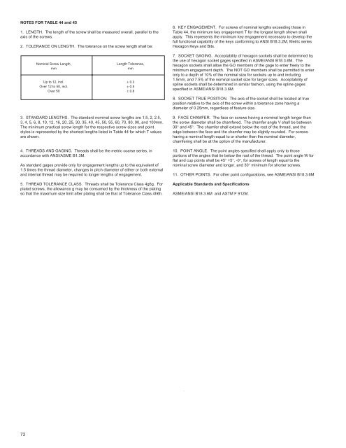
NOTES FOR TABLE 44 and 45<br />
1. LENGTH. The length of the screw shall be measured overall, parallel to the<br />
axis of the screws.<br />
2. TOLERANCE ON LENGTH. The tolerance on the screw length shall be:<br />
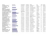
3. STANDARD LENGTHS. The standard nominal screw lengths are 1.5, 2, 2.5,<br />
3, 4, 5, 6, 8, 10, 12, 16, 20, 25, 30, 35, 40, 45, 50, 55, 60, 70, 80, 90, and 100mm.<br />
The minimum practical screw length for the respective screw sizes and point<br />
styles is represented by the shortest lengths listed in Table 44 for which T values<br />
are shown.<br />
4. THREADS AND GAGING. Threads shall be the metric coarse series, in<br />
accordance with ANSI/ASME B1.3M.<br />
As standard gages provide only for engagement lengths up to the equivalent of<br />
1.5 times the thread diameter, changes in pitch diameter of either or both external<br />
and internal thread may be required to longer lengths of engagement.<br />
5. THREAD TOLERANCE CLASS. Threads shall be Tolerance Class 4g6g. For<br />
plated screws, the allowance g may be consumed by the thickness of the plating<br />
so that the maximum size limit after plating shall be that of Tolerance Class 4h6h.<br />
72<br />
Nominal Screw Length,<br />
mm<br />
Up to 12, incl.<br />
Over 12 to 50, incl.<br />
Over 50<br />
Length Tolerance,<br />
mm<br />
± 0.3<br />
± 0.5<br />
± 0.8<br />
6. KEY ENGAGEMENT. For screws of nominal lengths exceeding those in<br />
Table 44, the minimum key engagement T for the longest length shown shall<br />
apply. This represents the minimum key engagement necessary to develop the<br />
full functional capability of the keys conforming to ANSI B18.3.2M, Metric series<br />
Hexagon Keys and Bits.<br />
7. SOCKET GAGING. Acceptability of hexagon sockets shall be determined by<br />
the use of hexagon socket gages specified in ASME/ANSI B18.3.6M. The<br />
hexagon sockets shall allow the GO members of the gage to enter freely to the<br />
minimum engagement depth. The NOT GO members shall be permitted to enter<br />
only to a depth of 10% of the nominal size for sockets up to and including<br />
1.5mm, and 7.5% of the nominal socket size for larger sizes. Acceptability of<br />
spline sockets shall be determined in similar fashion, using the spline gages<br />
specified in ASME/ANSI B18.3.6M.<br />
8. SOCKET TRUE POSITION. The axis of the socket shall be located at true<br />
position relative to the axis of the screw within a tolerance zone having a<br />
diameter of 0.25mm, regardless of feature size.<br />
9. FACE CHAMFER. The face on screws having a nominal length longer than<br />
the screw diameter shall be chamfered. The chamfer angle V shall be between<br />
30° and 45°. The chamfer shall extend below the root of the thread, and the<br />
edge between the face and the chamfer may be slightly rounded. For screws<br />
having a nominal length equal to or shorter than the nominal diameter,<br />
chamfering shall be at the option of the manufacturer.<br />
10. POINT ANGLE. The point angles specified shall apply only to those<br />
portions of the angles that lie below the root of the thread. The point angle W for<br />
flat and cup points shall be 45° +5°, -0°, for screws of length equal to the<br />
nominal screw diameter and longer, and 30° minimum for shorter screws.<br />
11. OTHER POINTS. For other point configurations, see ASME/ANSI B18.3.6M<br />
Applicable Standards and Specifications<br />
ASME/ANSI B18.3.6M and ASTM F 912M.