Consolidated Tech Man - Holo-Krome
Consolidated Tech Man - Holo-Krome
Consolidated Tech Man - Holo-Krome

Create successful ePaper yourself
Turn your PDF publications into a flip-book with our unique Google optimized e-Paper software.
NOTES FOR TABLE 1 CONTINUED<br />
2. THREAD LENGTH. L T Thread length of the screw is the distance from<br />
the extreme point to the last complete or full form thread. See page 3 for<br />
grip and body lengths of standard length screws. L T max. in Table 1 refers<br />
to longer than standard length screws.<br />
3. BODY. L B The unthreaded cylindrical portion of the shank for screws<br />
that are not threaded to the head.<br />
4. HEAD DIAMETER. Heads may be made plain or knurled at <strong>Holo</strong>-<br />
<strong>Krome</strong>'s option unless specified on the order. For knurled screws, the<br />
maximum head diameter includes the knurling. Minimum head diameter<br />
is the diameter of the head before knurling, or any unknurled section or<br />
band on the head.<br />
HEAD CONCENTRICITY. The heads of <strong>Holo</strong>-<strong>Krome</strong> Cap Screws are<br />
concentric with the shank within 1% of the basic screw diameter, D<br />
maximum (2% total runout), or 0.006 inch total runout, whichever is<br />
greater, when held within one diameter of the head but beyond the fillet.<br />
5. SOCKET CONCENTRICITY. <strong>Holo</strong>-<strong>Krome</strong> Sockets are concentric with<br />
the shanks of the cap screws within 1-1/2% of the basic screw diameter,<br />
D maximum, (3% total runout), or 0.005 inch, whichever is greater for<br />
screws through a nominal size of 1/2 inch. Sizes above 1/2 inch have<br />
sockets concentric with the shank within 3% of the basic screw diameter,<br />
D maximum, (6% total runout). See page 13 for socket tolerances.<br />
6. BEARING SURFACE. The plane of the bearing surface is perpendicular<br />
to the axis of the screw within a maximum deviation of 1 degree.<br />
7. THREADS AND GAGING. Threads are Unified Standard radius root.<br />
On screws with a nominal size 0 through 1 inch inclusive, threads are<br />
Class 3A in both UNRC and UNRF. On nominal sizes over 1 inch, threads<br />
are made to Class 2A in both UNRC or UNRF. <strong>Holo</strong>-<strong>Krome</strong> screw threads<br />
have controlled radius roots and radiused runout for greater fatigue life.<br />
Acceptability of screw threads shall be based on System 22 of ANSI/<br />
ASME B1.3M.<br />
Class 3A threads do not provide a plating allowance. When plating is<br />
required, it is recommended that <strong>Holo</strong>-<strong>Krome</strong> supply the parts plated.<br />
8. SCREW POINT CHAMFER. The point shall be flat or slightly concave<br />
and chamfered. The plane of the point shall be approximately normal to<br />
the axis of the screw. The chamfer shall extend slightly below the root of<br />
the thread and the edge between the flat and chamfer may be slightly<br />
rounded. The included angle of the point should be approximately 90<br />
degrees. Chamfering of screw sizes up to and including size 8 (0.164 in.)<br />
shall be optional.<br />
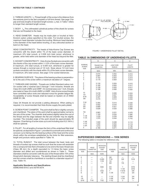
9. FILLET. For all lengths of screws the form of the underhead fillet shall<br />
be optional, as depicted in Figure 1, provided it is a smooth and continuous<br />
concave curve fairing into the bearing surface of the head and the screw<br />
shank within the envelope established by the limits for fillet extension,<br />
length and juncture radius specified in Table 1A.<br />
10. TOTAL RUNOUT. The total runout between the head, body and<br />
threads of socket cap screws shall be such that the screw will assemble<br />
into a compound hole that is threaded at one end to the basic thread size<br />
(Class 3B min.) for a depth equivalent to 1.5 times the basic screw<br />
diameter and drilled and counterbored as shown in Table 3. These<br />
diameters shall be concentric with the axis of the thread within 10% of the<br />
thread pitch diameter tolerance. The starting thread shall be chamfered<br />
and the corners shall be chamfered or rounded to a diameter equal to F<br />
max. Table 1A.<br />
Applicable Standards and Specifications<br />
ASME/ANSI B18.3 and ASTM A574<br />
2<br />
TABLE 1A DIMENSIONS OF UNDERHEAD FILLETS<br />
NOMINAL<br />
SCREW<br />
SIZE<br />
0<br />
1<br />
2<br />
3<br />
4<br />
5<br />
6<br />
8<br />
10<br />
1/4<br />
5/16<br />
3/8<br />
7/16<br />
1/2<br />
5/8<br />
3/4<br />
7/8<br />
1<br />
1-1/8<br />
1-1/4<br />
1-3/8<br />
1-1/2<br />
1-3/4<br />
2<br />
SUPERSEDED DIMENSIONS — 1936 SERIES<br />
The following table is included for reference only.<br />
NOMINAL<br />
SIZE<br />
0<br />
1<br />
2<br />
3<br />
4<br />
5<br />
6<br />
8<br />
10<br />
1/4<br />
5/16<br />
HEAD<br />
DIAMETER<br />
HEXAGON<br />
SOCKET<br />
SIZE<br />
MAX. NOM.<br />
—<br />
—<br />
—<br />
—<br />
—<br />
—<br />
—<br />
—<br />
—<br />
—<br />
7/16<br />
FIGURE 1 UNDERHEAD FILLET DETAIL<br />
B<br />
TRANSITION<br />
DIAMETER<br />
MAX.<br />
0.074<br />
0.087<br />
0.102<br />
0.115<br />
0.130<br />
0.195<br />
0.158<br />
0.188<br />
0.218<br />
0.278<br />
0.347<br />
0.415<br />
0.494<br />
0.552<br />
0.689<br />
0.828<br />
0.963<br />
1.100<br />
1.235<br />
1.370<br />
1.505<br />
1.640<br />
1.910<br />
2.180<br />
—<br />
0.050<br />
1/16<br />
—<br />
5/64<br />
—<br />
3/32<br />
1/8<br />
—<br />
—<br />
7/32<br />
NOMINAL<br />
SIZE<br />
3/8<br />
7/16<br />
1/2<br />
5/8<br />
3/4<br />
7/8<br />
1<br />
1-1/8<br />
1-1/4<br />
1-3/8<br />
1-1/2<br />
R E<br />
JUNCTURE<br />
RADIUS<br />
MIN.<br />
0.002<br />
0.003<br />
0.003<br />
0.004<br />
0.004<br />
0.005<br />
0.005<br />
0.006<br />
0.006<br />
0.007<br />
0.009<br />
0.012<br />
0.014<br />
0.016<br />
0.021<br />
0.025<br />
0.031<br />
0.034<br />
0.039<br />
0.044<br />
0.048<br />
0.052<br />
0.062<br />
0.071<br />
HEAD<br />
DIAMETER<br />
MAX.<br />
—<br />
5/8<br />
—<br />
7/8<br />
1<br />
1-1/8<br />
1-5/16<br />
1-1/2<br />
1-3/4<br />
1-7/8<br />
2<br />
FILLET<br />
LENGTH<br />
MAX.<br />
0.012<br />
0.012<br />
0.014<br />
0.014<br />
0.015<br />
0.017<br />
0.017<br />
0.020<br />
0.024<br />
0.024<br />
0.029<br />
0.034<br />
0.039<br />
0.044<br />
0.054<br />
0.066<br />
0.075<br />
0.085<br />
0.094<br />
0.102<br />
0.110<br />
0.119<br />
0.136<br />
0.153<br />
HEXAGON<br />
SOCKET<br />
SIZE<br />
NOM.<br />
—<br />
5/16<br />
—<br />
—<br />
9/16<br />
9/16<br />
5/8<br />
3/4<br />
3/4<br />
3/4<br />
—<br />
9