PE22 / ELC - eta plus electronic GmbH
PE22 / ELC - eta plus electronic GmbH
PE22 / ELC - eta plus electronic GmbH

Create successful ePaper yourself
Turn your PDF publications into a flip-book with our unique Google optimized e-Paper software.
3 Installation page 11<br />
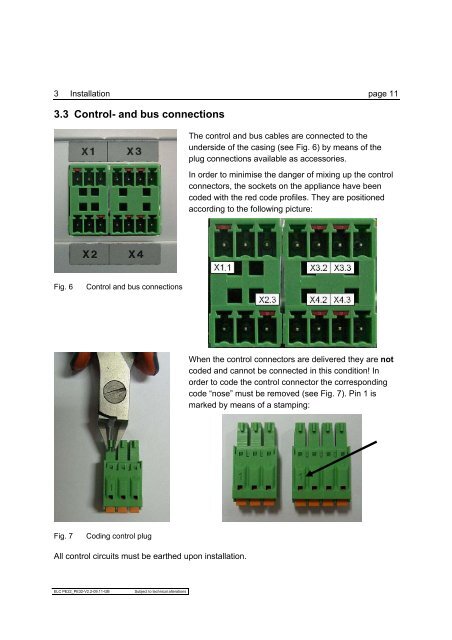
3.3 Control- and bus connections<br />
Fig. 6 Control and bus connections<br />
Fig. 7 Coding control plug<br />
All control circuits must be earthed upon installation.<br />
<strong>ELC</strong> <strong>PE22</strong>_PE32-V2.2-09.11-GB Subject to technical alterations<br />
The control and bus cables are connected to the<br />
underside of the casing (see Fig. 6) by means of the<br />
plug connections available as accessories.<br />
In order to minimise the danger of mixing up the control<br />
connectors, the sockets on the appliance have been<br />
coded with the red code profiles. They are positioned<br />
according to the following picture:<br />
When the control connectors are delivered they are not<br />
coded and cannot be connected in this condition! In<br />
order to code the control connector the corresponding<br />
code “nose” must be removed (see Fig. 7). Pin 1 is<br />
marked by means of a stamping: