Image Reconstruction for 3D Lung Imaging - Department of Systems ...
Image Reconstruction for 3D Lung Imaging - Department of Systems ...
Image Reconstruction for 3D Lung Imaging - Department of Systems ...
Create successful ePaper yourself
Turn your PDF publications into a flip-book with our unique Google optimized e-Paper software.
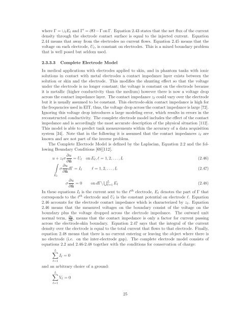
where Γ = ∪ℓEℓ and Γ ′ = ∂Ω −Γ on Γ. Equation 2.43 states that the net flux <strong>of</strong> the current<br />
density through the electrode contact surface is equal to the injected current. Equation<br />
2.44 means that away from the electrodes no current flows. Equation 2.45 means that the<br />
voltage on each electrode, Uℓ, is constant on electrodes. This is a mixed boundary problem<br />
that is well posed but seldom used.<br />
2.3.3.3 Complete Electrode Model<br />
In medical applications with electrodes applied to skin, and in phantom tanks with ionic<br />
solutions in contact with metal electrodes a contact impedance layer exists between the<br />
solution or skin and the electrode. This modifies the shunting effect so that the voltage<br />
under the electrode is no longer constant; the voltage is constant on the electrode because<br />
it is metallic (higher conductivity than the medium) however there is now a voltage drop<br />
across the contact impedance layer. The contact impedance zℓ could vary over the electrode<br />
but it is usually assumed to be constant. This electrode-skin contact impedance is high <strong>for</strong><br />
the frequencies used in EIT, thus, the voltage drop across the contact impedance is large [72].<br />
Ignoring this voltage drop introduces a large modeling error, which results in errors in the<br />
reconstructed conductivity. The complete electrode model includes the effect <strong>of</strong> the contact<br />
impedance and is accordingly the most accurate description <strong>of</strong> the physical situation [112].<br />
This model is able to predict tank measurements within the accuracy <strong>of</strong> a data acquisition<br />
system [34]. Note that in the following it is assumed that the contact impedances zℓ are<br />
known and are not part <strong>of</strong> the inverse problem.<br />
The Complete Electrode Model is defined by the Laplacian, Equation 2.2 and the following<br />
Boundary Conditions [69][112].<br />
u + zℓσ ∂u<br />
∂ˆn = Uℓ on Eℓ,ℓ = 1,2,... ,L (2.46)<br />
�<br />
Eℓ<br />
σ ∂u<br />
∂ˆn dΓ = Iℓ ℓ = 1,2,... ,L (2.47)<br />
σ ∂u<br />
∂ˆn = 0 on dΓ\� L<br />
ℓ=1 Eℓ<br />
(2.48)<br />
In these equations Iℓ is the current sent to the ℓ th electrode, Eℓ denotes the part <strong>of</strong> Γ that<br />
corresponds to the ℓ th electrode and Uℓ is the constant potential on electrode ℓ. Equation<br />
2.46 accounts <strong>for</strong> the electrode contact impedance which is characterized by zℓ. Equation<br />
2.46 means that the measured voltages on the boundary consist <strong>of</strong> the voltage on the<br />
boundary plus the voltage dropped across the electrode impedance. The outward unit<br />
normal term, ∂u<br />
∂ˆn , means that the contact impedance is only a factor <strong>for</strong> current passing<br />
across the electrode-skin boundary. Equation 2.47 says that the integral <strong>of</strong> the current<br />
density over the electrode is equal to the total current that flows to that electrode. Finally,<br />
equation 2.48 means that there is no current entering or leaving the object where there is<br />
no electrode (i.e. on the inter-electrode gap). The complete electrode model consists <strong>of</strong><br />
equations 2.2 and 2.46-2.48 together with the conditions <strong>for</strong> conservation <strong>of</strong> charge:<br />
L�<br />
Iℓ = 0<br />
ℓ=1<br />
and an arbitrary choice <strong>of</strong> a ground:<br />
L�<br />
Vℓ = 0<br />
ℓ=1<br />
25


