Sanitation, heating, air-conditioning (PDF / 6,4 MB - BTI
Sanitation, heating, air-conditioning (PDF / 6,4 MB - BTI
Sanitation, heating, air-conditioning (PDF / 6,4 MB - BTI
- TAGS
- sanitation
- heating
- en.bti.de

Create successful ePaper yourself
Turn your PDF publications into a flip-book with our unique Google optimized e-Paper software.
www.<strong>BTI</strong>-GROUP.COM<br />
07<br />
C<br />
Attention:<br />
Assembly clips for fixing the clamping pads must be<br />
ordered separately!<br />
With 45° anchoring, observe at least<br />
15 mm distance<br />
�����<br />
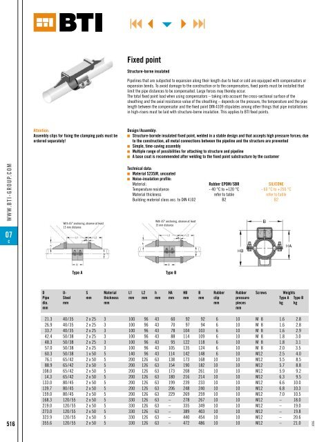
Fixed point<br />
Structure-borne insulated<br />
With 45° anchoring, observe at least<br />
15 mm distance<br />
Type A Type B<br />
Pipelines that are subjected to expansion along their length due to heat or cold are equipped with compensators or<br />
expansion bends. To avoid damage to the construction or to the compensators, fixed points must be installed that<br />
limit the pipe distances to be compensated. Large forces may thereby occur.<br />
The total fixed point load when using compensators – taking into account the cross‑sectional surface of the<br />
sheathing and the axial resistance value of the sheathing – depends on the pressure, the temperature and the pipe<br />
length between the compensator and the fixed point DIN 4109 stipulates among other things that pipe installations<br />
in high‑risers must be laid with structure‑borne insulation. This applies to <strong>BTI</strong> fixed points.<br />
Design/Assembly:<br />
g Structure-bornde insulated fixed point, welded in a stable design and that accepts high pressure forces; due<br />
to the construction, all metal connections between the pipeline and the structure are prevented<br />
g Simple, time-saving assembly<br />
g Multiple range of possibilities for attaching to structure and pipeline<br />
g A base coat is recommended after welding to the fixed point substructure by the customer<br />
Technical data:<br />
g Material S235JR, uncoated<br />
g Noise-insulation profile:<br />
Material: Rubber EPDM/SBR SILICONE<br />
Temperature resistance - 40 °c to +120 °c - 60 °c to +250 °c<br />
Material thickness refer to table refer to table<br />
Building material class acc. to DIN 4102 B2 B2<br />
D U- S Material L1 L2 h HA HB B Rubber Rubber Screws weights<br />
Pipe Steel mm thickness mm mm mm mm mm mm clip pressure Type A Type B<br />
dia. mm mm mm pieces kg kg<br />
mm mm<br />
21.3 40/35 2 x 25 3 100 96 43 60 92 92 6 10 M 8 1.6 2.8<br />
26.9 40/35 2 x 25 3 100 96 43 70 97 94 6 10 M 8 1.6 2.8<br />
33.7 40/35 2 x 25 3 100 96 43 78 104 103 6 10 M 8 1.6 2.9<br />
42.4 50/38 2 x 25 3 100 96 43 88 114 109 6 10 M 8 1.8 3.0<br />
48.3 50/38 2 x 25 3 100 96 43 95 122 118 6 10 M 8 1.8 3.1<br />
57.0 50/38 2 x 25 3 100 96 43 105 135 124 6 10 M 8 2.0 3.5<br />
60.3 50/38 1 x 50 5 140 96 43 114 142 148 6 10 M12 2.5 4.0<br />
76.1 65/42 2 x 50 5 200 126 63 138 173 168 10 10 M12 5.5 8.5<br />
88.9 65/42 2 x 50 5 200 126 63 154 190 182 10 10 M12 5.7 8.8<br />
108.0 65/42 2 x 50 5 200 126 63 173 208 261 10 10 M12 5.9 9.2<br />
14.3 65/42 2 x 50 5 200 126 63 180 216 214 10 10 M12 6.3 9.5<br />
133.0 80/45 2 x 50 5 200 126 63 199 239 233 10 10 M12 6.6 10.0<br />
139.7 80/45 2 x 50 5 200 126 63 206 248 240 10 10 M12 6.8 10.3<br />
159.0 80/45 2 x 50 5 200 126 63 229 269 259 10 10 M12 7.0 10.5<br />
168.3 120/55 2 x 50 5 330 126 63 – 278 267 10 10 M12 – 18.0<br />
219.0 120/55 2 x 50 5 330 126 63 – 335 349 10 10 M12 – 19.0<br />
273.0 120/55 2 x 50 5 330 126 63 – 389 403 10 10 M12 – 19.8<br />
323.9 120/55 2 x 50 5 330 126 63 – 440 454 10 10 M12 – 20.6<br />
516 355.6 120/55 2 x 50 5 330 126 63 – 472 486 10 10 M12 – 21.0<br />
1006