Diploma thesis
Diploma thesis
Diploma thesis

Create successful ePaper yourself
Turn your PDF publications into a flip-book with our unique Google optimized e-Paper software.
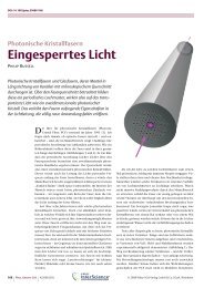
Figure 3.6: Different Λ Figure 3.7: Higher order phasematching<br />
Eq. 3.30 also reveals that the square wave grating orders provide several phasematching<br />
curves, m = ±1 as the two main periods and several higher order grating<br />
periods m = ±3, ±5, ±7 . . . some of which are visualized in figure 3.7. However the<br />
higher order modes are suppressed by 1<br />
m<br />
in amplitude. Additionally, these higher<br />
order phasematching modes soon drift into regions, where the produced photons<br />
can’t be detected any more.<br />
Waveguides<br />
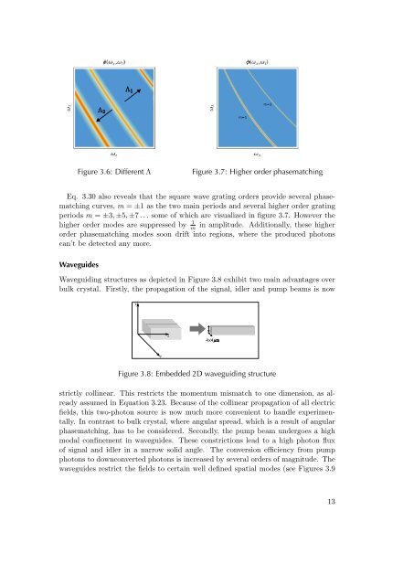
Waveguiding structures as depicted in Figure 3.8 exhibit two main advantages over<br />
bulk crystal. Firstly, the propagation of the signal, idler and pump beams is now<br />
Figure 3.8: Embedded 2D waveguiding structure<br />
strictly collinear. This restricts the momentum mismatch to one dimension, as already<br />
assumed in Equation 3.23. Because of the collinear propagation of all electric<br />
fields, this two-photon source is now much more convenient to handle experimentally.<br />
In contrast to bulk crystal, where angular spread, which is a result of angular<br />
phasematching, has to be considered. Secondly, the pump beam undergoes a high<br />
modal confinement in waveguides. These constrictions lead to a high photon flux<br />
of signal and idler in a narrow solid angle. The conversion efficiency from pump<br />
photons to downconverted photons is increased by several orders of magnitude. The<br />
waveguides restrict the fields to certain well defined spatial modes (see Figures 3.9<br />
13